Did you always wish you had a gun? Well just make one for yourself!
Somewhere in the video I mentioned it was a “Rail Gun”, but it is actually a coil gun. They both work with magnetic force, but differently.
Here I describe the detail design of the coil gun, so you may turn away if you hate details:
Basically as we all know, when we turn on or energize a coil, it starts attracting ferromagnetic material, in my case a steal bullet I made.
The issue is that if we keep the coil on, it keeps attracting the bullet. So what happens is that the bullet accelerates towards the coil and as soon as the magnetic center of the bullet reaches the magnetic center of the coil, the force of the coil over the bullet becomes zero. But as the bullet has momentum, it passes the center, at which point the coil starts pulling it back and decelerating the bullet, or accelerate it back towards the center.
You see in the video that this results in the bullet oscillating as if it was attached to a spring, and eventually stops at the center.
So the best way to make sure the bullet reaches maximum speed is to turn the coil off as soon as it reaches the magnetic center of the coil. If the coil and bullet are both symmetrical, their magnetic center will be the same as their physical center.
There are two ways to do it: one is to perfectly time the turn-off moment of the coil, or another easy way is to use a sensor and detect when the bullet reaches a sweet spot to turn the coil off.
In some designs they just use capacitors and discharge them in a coil and the capacitor runs out of charge quick. This way the coil won’t have time to pull the bullet back, which is sort of like timing the coil.
The problem with all the timing designs in my opinion is that it is not possible to easily predict the required time to keep the coil on, as it depends on the bullet mass, coil field, original distance of the bullet from the coil and etc… and therefore the coil either turns off too early or too late, both resulting in a slower bullet.
So I believe to make the on time of the coil independent to all these factors, the best way is to have a sensor and detect the location of the bullet and turn it off on time.
In my design, to turn the coil off I placed an infrared (also known as optical) sensor to detect the tip of the bullet right where their centers meet, and this would turn the coil off using a simple circuit.There are other options for the sensor such as Hall Effect sensors, which can be much faster. You need a fast response time as any delay in response will cause the bullet to pass the center and result in some deceleration. Especially when you have many coils rather than one, the speed of the bullet in the final stages is super fast.
The following circuit is what I designed and made.
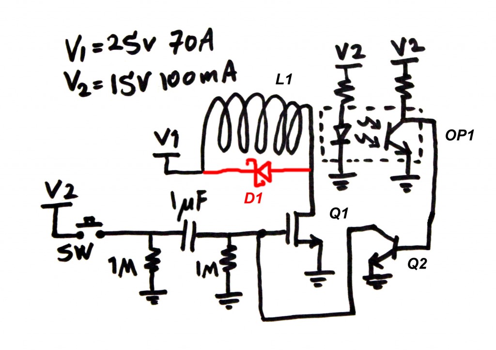
In the circuit above I have added D1, which I forgot to show within the video. Not having this diode caused me grief and explosions which I didn’t capture on video!
This circuit is just a quick way of doing it for demonstration that came to my mind. It is by no means the best way to do it. Especially since the infrared sensor I have has limited response time (3kHz).
I purchased the parts from Digikey and here’s their part numbers for your reference (you may choose your own):
OP1: EE-SX1070 from Omron
Q1: IRF7739L2TR1PBF from International Rectifier
Q2: Generic 2N3904 NPN Transistor or similar
D1: Generic Schottky Diode Capable of >30V, >10A
SW: Generic push button, normally open
R and C: Generic
L1: Hand wound
Here’s the circuit description:
Q1 transistor is basically the switch that turns the L1 inductor on and off. When Q1 turns off, L1 will try to release the energy stored in it by continuing the current in the same direction. Without D1 this would cause the voltage at the drain of Q1 to jump to a huge number breaking Q1 and shorting it. This will short the supply through Q1 and will result in exploding Q1 and damaging the coil. Having D1, when Q1 turns of D1 turns on closing the loop of the current and protecting Q1. Another side effect is reversing the magnetic polarity of L1 that could help accelerating the bullet.
When the switch SW closes, it sends a high level voltage through the 1uF capacitor to the gate of Q1 turning it on. The 1M ohm resistor will help discharging the 1uF capacitor.
OP1 must be biased such that when the sensor is not blocked, the transistor output is at a low voltage below 0.4V to make sure Q2 is off, and when the bullet comes into the sensor blocking the infrared light, the optocoupler transistor output jumps above 0.7V turning the Q2 transistor on.
So Basically when the switch SW is pressed, the gate voltage of Q1 jumps, turning it on. This will attract the bullet into the coil and as soon as the bullet reaches the sensor, Q2 turns on pulling the gate of Q1 low and turning it off.
And it works as good as you saw in the video. There are some issues with this design though. If there is no bullet inside and the trigger is pressed, the gate voltage of Q1 drops as the capacitor at the gate is discharges by the 1M Ohm resistor. At some point this results in increment of the Q1 drain-source resistance, meaning a high power drop across Q1 that will blow it up. So there should always be a bullet. We can’t remove the 1M Ohm resistor because without it the gate voltage may never return to 0 volt.
Like I said, this circuit is only for demonstration and a better and faster circuit could work much more reliably. But the functional concept remains the same.
Now more coils can be put together in series, everyone with its own fast sensor. The bullet can be smaller and more light weight to help accelerating faster. Also there can be different ways to turn the series coils on and off. For example:
- They can turn on and off one at a time, as soon as the first coil turns off, the second one turns on and so forth.
- They can turn on two at a time. For example if we have 4 coils from L1 to L4, L1 and L2 can turn on together. As soon as the bullet reaches between L1 and L2, L1 turns off and L3 turns on, This way there can be better acceleration, but more power usage.
- All coils can turn on together, but turn off one at a time as the bullet passes them.
And the rule of thumb is: the more number of winding and more power over coil (voltage and current) the greater acceleration of the bullet. Also of course turning the coil off at the perfect spot is very important too.
I hope you like what you read. If not, please drop a comment and I will write some update when I can. Thanks and stay safe!

Fantastic videos and humor – keep it up – you are the best!
just an observation:
I doubt the optical sensor is slow for this application. I think the magnetic field in the coil decays slowly after shutdown especially with the necessary D1, that current keeps flying around the coil as a coil does not like changes in current (just like your Capacitor doesn’t like changes in voltage). There is no way of shutting down that current as it will cause several KV on the Mosfet -you must have blown many as these are rated at 40V and you didn’t have D1 in your video!
One hack would be to wind another coil and place it on the output of the first coil but wound the other way so its NS is flipped from the first coil and wire this one between D1 and V1. Therefore the flyback current of L1 will flow through L2 and negate the decelerating power of L1!
More fun videos please you are a genius!
Hi Mehdi,
I’m trying to make a coil gun, and before i start, i just want a little advice. For instance;
1)How do you make the IR sensor?
2)How many volts of electricity did you supply for the coil?
3)How did you make the bullet?
4)What is the length of the bullet and the coil?
5)If you put a barrel around the coils, does it have to be insulated?
I will be extremely gratefull of youre reply.
1) you buy the IR sensor, not make it. Then you need to bias it properly. It is like a transistor, for a certain input current you get a certain output current. In normal condition the output is on, or like a switch it is closed. Then when something like a bullet goes in there, it opens.
2) I put 30V I believe, but that is not as important as the current I supplied, which was 70A or more.
3) I machined it in the machine shop at work.
4) the coil is around 4cm and the bullet is about 5cm in my case. It is not mandatory though.
5) you don’t need to isolate teh barrel, just make sure it doesn’t short anything!
Good luck
Dear Mr Mehdi,
with your permission, i would like to make this my control and measurement lab project. if you can please mail me your address so we can talk about ways to modify this design. i hope to have your reply soon.
Do as you wish. But I won’t be able to do your lab project! Good luck!
thank you for your reply, i was not asking you to do my project. but hoping you would give me some advice on how to make it a little more complicated.
You can make it exponentially more difficult by just adding a second coil to it! The third one would even be harder! Good luck.
i am trying to build this coil for a gun and for door locks and i have wrapped 16 awg magnet wire around pvc with a 1/2 inch hole and bullet size i have used six 9-volt batteries in series trying to get any kind of magnetic pull on the bullet i have even tried supplying power to my 3 pound spool of wire and still no magnetic pull of any sort have been working on trying to get this work for a couple days and i am at wits end i dont know what im doing wrong please email me with some help i would greatly appreciate it thanks
Keaton
Hi Keaton,
First, 9V batteries cannot generate any decent current. Imagine I was using 70A, and the 9V battery can maybe generate 0.5A at best. If you instead use a car battery, you will get a huge pull, and maybe your coil burns too because those can generate even 500A. One thing you can do is to have a huge capacitor parallel to your 9V batteries so that the capacitor can handle the short spike of high current. Use camera flash capacitors. If you like to move a door lock, you don’t need great pull and acceleration. Then use many more turns of lower gauge wire and then you can generate good pull with much lower current.
If I wanted to test the affect of varied voltage to the final speed of the projectile, where would be the best place to vary the voltage and by what means?
Thanks
You should vary the voltage across the coil. Basically it is the current that creates the magnetic field. The amount of current also depends on the voltage across the coil, the coil and switch resistance.
What was the gauge and material of your coil? And how long was it before you wrapped it?
It was AWG 18 copper magnet coil. I don’t know how long the length was. I just wound it until I was tired!
Where do you get the circuit boards you construct the circuits on?
What power supply are you using to get 25V 70A on V1? Thanks.
Pingback: Video tutorial: come costruirsi una pistola in casa | cose strane
http://www.youtube.com/watch?v=MFohadroheM
Hello, I just came across a startling video that had me quite speechless upon watching it. Now I admit it, I didn’t fully understand this video as I’m a physician and electricity is not my field of expertise, however I do know enough to realize this is not a hoax or bogus and has in fact validity… and I could not think of anyone better than you to send it to… surely you might enjoy watching this video… god speed
Hi Saviz,
All I can say is that this person has little knowledge of electricity as most of his comments don’t make sense electrically. It is possible to capture ambient energy, but this circuit is not the way to do it. Also beside sun’s light source and wind (which is also created thanks to the Sun) all other ambient energies radiated in the environment are extremely low in energy. So, there is no secret in this circuit!
Hi!
Not an EE. How big a of a coil would I need to make if I wanted to use 1F caps? Can relays be fast enough for switching multiple coils?
That’s a complicated problem. The optimum time you want to keep the inductor on would depend on the length, thickness and weight of the bullet as well as the current flowing into the coil, the resistance of the coil and many more things. A relay won’t be fast enough for multiple coils. Relays switch around 10 mS and that would decelerate the bullet.
You are correct. And there is an RC on the gate of the transistor, the 1uF capacitor and the 1M resistor. It does what you say, but it may turn it off too late. As I said, this circuit is not the best, but good enough for presentation.
Hello Mehdi, I love your videos and I hope you continue to make more. Informative and hilarious! As I understand it, you must have a bullet or else the coil will never turn off, which will cause damage to the rest of the circuit via over current. Would it be feasible (or wise) to attach an RC circuit to the base of Q2, causing it to turn off no matter what after a certain time? To be clear, could you have an RC circuit charge up when SW1 is pressed, but programmed in time that it would turn off the coil a little after the bullet should have passed? Just a thought, I am still very much learning.
How much did it cost to build the circuit?
Why a zener diode and not just a diode?
It’s not a Zener, it is a schottky diode. schottky diode is fast and will respond quick to spikes avoiding the transistor to break.
Would a hall effect sensor work considering the magnetic field created by the coils? I would think there would be too much interference for it to be effective at detecting the bullet
HI
or do u use a ceramic capacitor? whats better ah aluminium electrolytic or ah ceramic?
Hi! i had a question! in what direction do u mount the capacitor? i know its ah neerdy question but i dont wont to blow it up! i think the minus side right when i look at the drawing or not?
Best video I’ve seen in a long time, keep up the amazing work
what resistors do u use by the ir sensor?
around 1k on the LED side and 22k on the transistor side.
When will engineers be able to clearly articulate their ideas ???
Which part of this video did you not understand?
Pingback: Watch This Man Shoot And Electrocute Himself As He Demonstrates A Coil Gun | Gizmodo Australia
I watched your video and read this article, and went to the website you mentioned. But I couldn’t find the IR sensor any where.
Here it is:
http://www.digikey.com/product-search/en?x=0&y=0&lang=en&site=us&KeyWords=EE-SX1070
I really sorry to you.. but seriously you made my day
god bless you
If i change the voltage values , how can i get the new values of resistors and the capacitor ?
You don’t need to change the resistor and capacitor on the gate of the FET. You just need to make sure you don’t raise V2 too much to break the gate of the FET, which is usually 20V max. You may need to tune the resistors of the Optocoupler to make sure the output still saturates.
I wanna ask you something. I really try to do this but 1uF block DC. then no current on 1M so, Gate voltage is nearly zero and source voltage also then NMOS is off. Isn’t it? Also coil resistance should be low then how can you deal with the over current
1uF blocks DC. But when you close the switch, the voltage on one side of the 1uF jumps, resulting on the voltage on the other side to jump too as the capacitor likes to keep the voltage across it the same. So this will rise the gate voltage of the MOSFET high. If the switch is held on the gate voltage will slowly drop as the 1uF discharges through the 1M Ohm.
The coil resistance is very small, but not exactly zero. For example my coil resistance is around 0.250 ohm. So there will be some current limiting anyways. If the FET can take large currents for short period of time, it will be fine like mine. Just make sure you have a bullet going to turn the circuit off and otherwise teh FET will blow. Like I said my circuit works, but is not the best way to do it.
You have to make more videos! I laughed out loud when I saw both videos (Coil Gun, and ESD Gun).
It’s nice to see someone taking a dry subject matter and injecting some humor.
Thanks!
The part that Mehdi uses is actually an optical sensor. Datasheet here: http://www.omron.com/ecb/products/pdf/en-ee_sx1070.pdf
I love the videos! Early in the written description you say ‘RF sensor’ and I think you meant ‘IR Sensor’.
I was also thinking you could switch polarity on the coil to then push the steel rod. Thanks for clearing that up!
You are right. I though I fixed that once but it came back. I’ll fix it now.
Why don’t you use a capacitor to discharge into the coil wouldn’t it save a lot mot time ?
Like I explained, discharging a capacitor will be similar to a timer. The coil may discharge sooner or later than when the bullet reaches the center. It would work, but won’t be the best. Also the capacitor current drops rapidly causing the energy of the coil during acceleration. But instead using a high power supply, you can make sure the power is maximum throughout the acceleration.
ad more coils. make a real gun. fully auto and silent! so cool.
And I am here again.
Think I am thinking fundamentally wrong in that if run on AC it will ‘push’ on a half cycle as well as ‘pull’ in the first 1/2 cycle.
Whatever the polarity is I guess the bullet will be attracted to center.
Maybe a bar magnet then? And of course AC is not something very portable!
Dennis
Another comment Mehdi,
Will the gun work with considerably more turns and a lot less current?
70 amps is quite a power supply too. What do you use?
Maybe could use an ac supply where the voltage reversal does the switching?
It would mean the bullet needs to get to the center during a half cycle then be pushed out on the other half cycle. Not sure if I can work out the length of bullet and barrel for a 60 Hz supply. It seems the bullet is not critical here but the barrel very much so? It could maybe very much simplify the gun electronics although I can see a problem getting the bullet to start its motion in the right part of the sine wave!
The magnetic field is affected by higher current and higher number of turns. So if we can increase both, it would be great. But more current means a thicker wire so with the same number of turns, your coil size grows. I am using a wire , which is 16 AWG I believe. It can’t continuously take 70A, but it can easily handle a short burst of current. When you make a coil, it has a resistance. So for example if you have a 12V, it maybe able to only allow 50A even if your supply can allow 100A. So you will have to raise your supply voltage for more current.
I don’t thing you will get anything goo with AC. First the field will be alternating meaning an inconsistent power, and also if you are using a steal bullet, it doesn’t matter that the field gets reversed. It will swill attract the bullet back in.
Thanks you replies Mehdi.
I now what you mean trying to get a very large current through the wire’s resistance with a 12 v supply.
And appreciate now that if the coil is N or S it will still attract a steel bar. So reversing the current will not do any good after the bullet has got to the 1/2 way stage.
However if the bullet is a bar magnet and the coil polarity was reversed at the 1/2 way stage, could that not be used to advantage? It would be sensitive to the polarity of the coil.
Still needs a sensor that can detect the bullet though 1/2 way through the barrel. A pvc one could probably use a Hall effect sensor.
Dennis
It is possible to use a bar magnet and reverse the polarity. You would need to find sweet spots to reverse the polarity and also still time it well too. I haven’t done this before but I’m guessing it will not make things simpler. But you may achieve better acceleration.
You’re great at explaining Mehdi. And you are no mug!
Could it be that the circuit would work and give more velocity if there was just one coil but it was a lot longer.
Say a foot. Having thought about it though the bullet causes the sensor to switch off the current or ideally reverse the polarity. So the bullet would have to be a long one!
Unless the sensor could be a little over 1/2 way down the barrel and ‘see’ through it to the bullet. How about a Hall effect sensor?
Regards, Dennis.
Hi Dennis,
The issue with a longer coil is that you still need to turn it off when the bullet reaches the center, which renders the second half of the coil useless. And also the very long coil will not necessarily put more force over the bullet, for example my bullet can’t be over a centimeter away from the edge of the coil or it won’t attract it at all. So in a very long coil, only maybe around 5cm (2″) of the coil has real effect on the bullet. It would be much more effective to have 6x 2″ coils and turn them on/off correctly, rather than a 1 foot coil.
You are teh best. Contitue.
Thanks!
what resistor do u use by the ir sensors?
around 1k on the LED side and 22k on the transistor side.