It is quite easy to listen to a conversation on a land line:
Let’s quickly go over how a land line works:
- There is a 48V DC with around 2kV series resistance on the phone lines that are called Tip and Ring
- When ringing, an AC voltage of around 65Vrms 20Hz is sent over your phone line. Typically the ringing cycle is On for 2 second and Off for 5 seconds.
- When your phone detects the ringing voltage it starts ringing and when you pick it up, or when you pick up the phone to make a call, your phone places a load of around 390 Ohm on the phone line. This load pulls the line voltage down by drawing current. The switching center detects this drop and knows your phone is off hook. If you were ringed, then the center establishes communication. But if you picked the phone to call, the center sends you the dial tone.
- When you are ringed, after the first ringing signal the center transmits caller ID data digitally to your phone which the phone usually displays on a LCD screen.
- The audio signal is an uncoded plain AC signal.
- When you dial, you either use:
- Pulse dialing (old style in rotary phones) which is basically quickly shorting and opening the tip and ring wires equal to the number you want to dial (10 shorts for 0), with a longer pause between the numbers.
- Tone dialing which is basically two audio sine waves super imposed, and indicate a single number depending on the frequency of tones. Switching centers accept both methods above.
- When you turn off the call, the line voltage jumps back up to 48V which indicates to the center that the call is finished.
- When you talk or being talked to, both audio signals are superimposed on the same line. There are filters in your phone to subtract your voice from the two signals so you can hear the incoming voice easily. Although a perfect subtraction is not needed as you are already hearing your voice through air.
- The audio frequency is filtered below 4kHz.
So basically listening to a call is quite simple. Like I said in the video, during an active call you don’t need to care for much. The line voltage is low (around 7V) and all you need is to isolate the DC using a capacitor and send the AC signal to a head set. The headsets typically have around 32 Ohm resistance per side. If you connect the line to both sides, it will load and attenuate the AC level more.
In active call, having a series single 100uF and >10V capacitor is enough to isolate the DC and send all frequencies into the head set, like below:
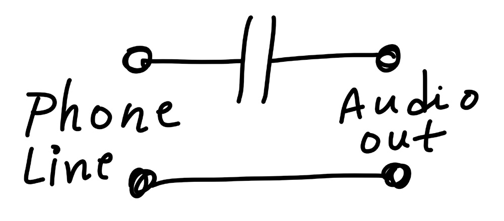
Single Capacitor Wiretapping
But you can’t just rely on a single capacitor to handle all protection and save your audio input, which in my case is my precious camera! The lines can have any polarity, the ringing voltage and the idle DC voltage are huge. And so I designed the circuit below:
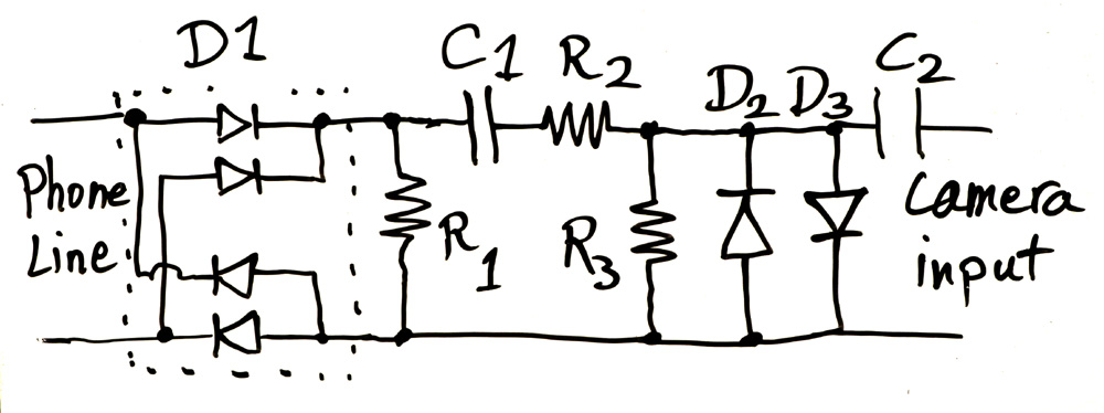
Wiretapping Circuit
Let me explain how it works.
- D1 is the FULL BRIDGE RECTIFIER! We need this to make sure no matter what the order of the wires are, we send the right side up DC voltage into the circuit. Puny single diode wouldn’t work here, because then the circuit would not work and will be off if the DC voltage is in reverse.
- The rectifier is typically used to make a DC voltage, but here we don’t want to rectify, we want the AC signal of the audio to go through. And that’s where R1 comes into effect. The diode D1 only outputs current one way which would charge C1 up to the maximum of the AC + DC signal. And so for any voltage below these when AC level goes into falling cycle or DC level drops for some reason, the diode turns off and the AC signal is cut off from the circuit. R1 makes sure C1 is discharged as the AC signal goes down and so the entire AC cycle goes through.
- But what is C1 for? It is of course to isolate the phone line’s DC voltage from the circuit and to only let the AC through.
- Then the AC signal goes through the R2 / R3 resistor divider, which in my case I divided the signal by a factor of ~3. Because per my measurement, the AC signal was a maximum of 3V peak to peak, or 1.5V amplitude. Dividing it by 3 would give me a 0.5V maximum peak for the signal. This would ensure that the AC is not distorted by my next stage, D2 and D3 diodes.
- D2 and D3 diodes are there to limit the AC peak level. For positive peaks above ~0.6V, D3 would conduct and clamp the voltage to around 0.6V to 0.7V, and for negative voltages, D2 would do the same. This way the AC amplitude wouldn’t rise above 0.7V peak, which would be safe for my camera input. And again this is why I divided the AC signal using R2 and R3 to have a maximum of 0.5V audio level, so that D2 and D3 won’t clamp and distort the audio. Basically D2 and D3 would clamp the ringing voltage, as well as any transients and ESD voltages coming in. Of course their clamping current is heavily limited through R2.
- And last but not the list, C2 isolates the DC voltage coming from the camera from the circuit which has a 0V DC. My camera outputs around 2V DC when recording, which would easily be clamped to 0.7V by D3 and pretty much destroys the AC audio signal too. But with C2, no clamping happens. The DC coming from the camera is to power electret microphones, and sometimes is also used as an indication by some microphones attached to the camera so they can detect when the camera is recording and wake up.
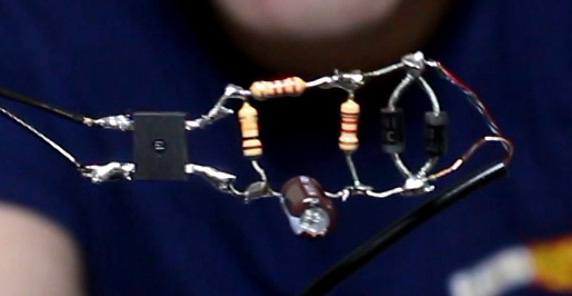
You see in my circuit below (before I added the C2 capacitor) I have moved the location of C1 to the bottom side, solely to make the circuit look more symmetrical. C1 is a series capacitor with the rest of the circuit anyway, and switching locations of series components will not affect the properties of the circuit.
Now you might like to know what are the proper values for these components. I can tell you the values I used which I picked based on feeling and what I had available that worked well, which are:
- A full bridge rectifier chip with not much current capability. I don’t have its part number, it is under the hot glue now! But any generic bridge would work.
- R1: 10kOhm
- C1: 1uF 50V (mind the polarity, must withstand the 48V DC)
- R2: 2.2kOhm
- R3: 1.2kOhm
- D2 and D3: Any generic all purpose rectifier diode, but I used 1N4001. Others like 1N400x (x=1 to 7) or 1N4148 or similar would work just fine.
- C2: 10uF 16V (mind the polarity)
Design Tips:
- To make sure you are passing low frequencies well enough, C1 x (R2 + R3) should be large enough as the circuit is a high pass filter. For example if the low frequency role-off is f = 100Hz, then f = 1/(2 x Pi x C1 x (R2 + R3)) would help you calculate. In my case R2 + R3 = ~3k. So C1 = 0.53uF and above would be fine. My value of 1uF seems pretty good here.
- R1 should draw the same or more current than that C1 was charged with during positive peak of AC signal. More current is fine, because the voltage across R1 only drops to a point where D1 turns on which results in C1 voltage following the AC input. The excess current is provided through the diode from input rather than discharging C1. But a smaller R1 current would be trouble, because then C1 would continue charging up and turning D1 off, clipping the AC input like a real DC rectifier. I guess some white board explanation would be good at this point! But anyway in my circuit if AC signal is at its maximum of 1.5V peak, this voltage over (R2 +R3) = 3k will result in 0.5mA charging C1. So we need more that that current through R1 to ensure C1 discharges properly without creating DC offset. We already have a 7.5V DC on phone line, which plus the 1.5V positive peak of the AC results in 9V. This voltage through the D1 diodes drops back to ~ 7.5V DC. 7.5V divided by our R1 of 10k would be 0.75mA, over the 0.5mA we need to properly discharge C1. Hey, my feeling was pretty on point there!
- Increasing C1 would help passing low frequencies better, but wouldn’t effect the charge/discharge current and so resistor values won’t need to adjust.
- C2 doesn’t need to be much. A value equal to C1 or more is fine because of high resistance input of the camera audio jack. But of course I don’t have an accurate measure if how much that input resistance is. If known, then C2 should be calculated better. Otherwise keep C2 a bit higher. If you are happy with your audio quality, then it is fine.
Make it wireless
Excellent video.
Hello
I agree very good video!
Is it it true the main reason for rectifying is to prevent reverse polarity of the electrolytic capacitor? If there was a practical high voltage non-polarized capacitor of that large of a value the need for rectification would go away and the DC blocking will still allow the AC to pass without damage.
Excellent video.
Great video
I am just wondering why the heading states:
There is a 48V DC with around 2kV series resistance on the phone lines that are called Tip and Ring
Resistance is written as ohms not voltage.
Aren’t telephone signals modulated?
How can the full bridge rectifier leave ac through?
A question about the circuit with just the capacitor, is it safe to leave it plugged in all the time?
If I want to play recording to a phone line, can I use the same circuit?
I not so much interested in wiretapping a phone line. What I want is a circuit that will detect the voltage drop when a phone is off hook and turn on a switch. Basically, I want to use a POTS phone with an old-school key system. The phone I want to use does not have extra terminals on the hook switch to connect the A and A1 terminals. So, a circuit that detects the voltage drop and short A and A1 would do the trick. Does anyone know of such a circuit?
Maybe an Arduino Microcontroller would do the trick. You could write some code where it could handle the incoming DC voltage, and monitor it constantly. Then, shove one wire into A1 and another to A, according to which one is which polarity, and then feed that into a relay. When the voltage drops, the Arduino could turn on the relay, closing the circuit. Presto!
Or, Maybe you can use a Opamp (Operation Amplifier) like a compartor betweents the voltages of the line, when the line is high (i mean 48v DC the op amp, doesn’t work; but when someone pick up the phone, the voltage of the line will be drop up to 16v, like the video show us) in that moment the circuit work
sorry for the grammar, my english is awfull (I’m not using google translate)
Now let’s design ◉ ___ ◉
Important article about How to Wiretap Phone Line with DIY Circuit and really usefull, keep posting! can i share it?
in the part of rectifier and capacitor you said “diode D1 only outputs current one way which would charge C1 up to the maximum of the AC + DC signal”
why there is an ac signal output from full bridge rectifier, i know there is a ripple voltage but i cannot think where ac signal came from from the out put of full bridge rectifier?
Yes, I was asking myself the same question! Anyone can help us?
When ringing, an AC voltage of around 65Vrms 20Hz is sent over your phone line. Typically the ringing cycle is On for 2 second and Off for 5 seconds.
it’s actually 90Vrms.. Not 65Vrms.. It depends where you are but the Bell System standard widely used today is 90Vrms..
Also multiple times you say ‘center’ where the phone lines go to the house, The correct word is Central Office or Telephone Exchange.
The Most common used Switches for POTS Landlines are 4ESS, 5ESS, DMS-10X & Soft Switches.
Typically when a Phone Line leaves a CO (Central Office) It has 55MA of Loop Current, By the time it reaches it’s location it should have at the least 23MA Of Loop current.
Also A Typical Phone Line will have 5 REN (Ringer Equivalence Number) measured in number of mechanical bells it can ring.
So 5 REN means you can connect 5 Vintage Rotary phones like a Western Electric 500 Set to the line and they would all ring, But the second you add a Sixth or Seventh it would stop.
Dear Electroboom,
I suggest you add another capacitor between R1 and R3 (on the ground side). This would prevent the possibility of ground loop current.
I’ve got a video idea for you ELECTROBOOM.
MagLev Trains and how all of there electrical systems work.
Thanks,
Scientist Smith
Hi, this is Scientist Smith and what electroboom teaches for how voltage kills is NOT true!!! This was in a video he made on March 10, 2014. I’m sorry to break the news but it is the amount of current that flows through the heart that kills. So what is current? Current is another word for Amperage and Amps. So Amperage kills. Please DO NOT be mis informed!
Thanks,
Scientist Smith
Well it is the current that kills but if you don’t have any voltage what’s gonna kill you? Nothing. You need voltage to have a current flow.
You could say the voltage pushes the current forward. If there’s nothing that pushes you don’t have any current.
Hello Medhi!
Besides my question, I want to say that I’m a huge fan and a subscriber.
Here goes my question:
How to I make my physics professor believe that in a lightning strike there’s like a
100,000,00 volts(million volts). She doesn’t belive me. She told me “The lightning strike CANNOT achieve a million volts because of the resistance of air”. I’ve seen the “7 million volt” episode, and by that knowledge how can I prove there’s a million volts(even more!) in a lightning strike?
Tell your teacher that 3,000,000 (3 Million Volts) is the Voltage breakdown of air. But just because the voltage breakdown of air (Under Controlled Conditions) is 3,000,000 volts does not mean that a voltage higher can travel from point A to point B. 2,000 volts or 2kV can arc across 1/4 of a centimeter (according to lab data not theoretical formulas) in dry air. Dry air is less conductive than moist air. According to lab test results that I have done with voltages above 20,000 volts. The results have showed yet another arc across air. (Note: This arc is without the kick start arc. Where the wire is touched then pulled away) What I would tell your teacher is that the breakdown voltage of air varies in a very very wide range. If you don’t believe me then why did 2,000 volts arc in air across 1/4 of a centimeter when the voltage breakdown of air in controlled conditions is 3,000,000 volts? Well that’s due to the wide range of conductivity and continuity of the connection between point A and point B. So in short: YES The voltage can range higher than 7,000,000 (million) volts. The more insulation between point A and point B means a higher voltage is needed to arc across that insulator. For example, there is a reason why there are thinly insulated wires called magnet wire with a very thin insulation on it V.S a 600 volt specified wire for high voltage. This high voltage wire has a very thick insulation between point A (being the wire) and point B. (being you) According to my controlled lab data I have found in my results that a 600 volt plastic insulation wires does not have a voltage breakdown at 600 or even 700 volts. It (in dry conditions) didn’t even have a voltage breakdown at 2,300 volts.
So the main thing your teacher should take away from this is this.
Voltage Breakdowns occur in a varied amount. And that a lightning bolt of electricity can have a higher voltage arc across point A and point B than the voltage breakdown. Results in wet weather may have a lower voltage. But it will not have results being any lower than 3,000,000 volts.
Thanks,
Scientist Smith
That is true
What is the 2kV series resistance ? is it a typo ?
oops
Hi,
Requesting you to provide your review on EMF shield mattress. Does this really work?
Please see below link to this product.
Blocking EMF: https://whisper-sleep.ae/whisper-sleep-protected/?gclid=CjwKCAjw_b3cBRByEiwAdG8WqvbE4e0UJrCHJplcupeCU0JX89SnRm87em7B49Wmmfdx-vMevOffpBoCQAYQAvD_BwE
Mehdi Sir which book would you suggest to an amateur to learn the basics of electricity from the scratch?
Mehdi Sir which book would you suggest to an amateur who want to learn the basic of electricity from scratch.
I would suggest looking online or searching for electricity basics in a PDF online. This is how I learned, but I reinforced my learning by going to real professions and masters in electricity and basically asked them if it was true. Then with the materials I can get my hands on, I simply tested it.
Thanks,
Scientist Smith
ElectroBOOM, is possible to turn on a led when rinning?
For example, a current limiter resistor and a LED in series with D2 or D3?
Hi I been trying to build something that will connect from my PC to the Headset of my home phone. So I can use a wireless Headset that is also connected to my PC.
I currently using Isolation Transformers between the input and output of my phone and PC but unfortunately I can hear my self with a >0.5 sec delay which can get annoying.
Any suggestions on how I can improve my setup?
But I think that not a good way.You say you want to use your PC ,right?But the video…no ,the passage only tell us that how to use….to…..So you must think or make explanation by yourself….
Mehdi, apparently this American railroad called Norfolk Southern has ac to dc conversion locomotives that are called the ac44c6m. They are rebuilt from the dash 8 40c made by GE
Hey Mehdi, I love your videos and decided to became a patreon as well. Your explanations about the theory stuff are really good and thorough, I was wondering did you only do bachelors in electrical engineering or you went for masters as well? I am an electrical engineering student from the states, I got 1 more year left and im inspired by the stuff you do.
Best of luck on your future endeavors
-Tim
Yeah,I also want to say this.I really love his video!!.It looks a bit fun…..Right?That is cool!!
Seems to work without the full bridge rectifier. Why it’s needed ?
Did you even read the article?
Besides, not really an ElectroBOOM project without a *FULL BRIDGE RECTIFIER* xD
The FULL BRIDGE RECTIFIER, is used to not matter the polarity of the input
Did you know that DC has a preferred polarity that is separated. BUT DID YOU ALSO KNOW that AC also has a preferred polarity. Yes AC Alternating Current has a preferred polarity and this can be demonstrated by using a magnet and a resistive solenoid hooked up to AC mains. When powered up this either repels or attracts the magnet more than the other polarity.
Thanks,
Scientist Smith
I have a VOIP connection. Will this work on that system?
No, because all telephone conversations are transmitted digitally, as the name says Voice over Internet Protokoll. Basically you phoneline is used only to transmit internet packages and the telephone signal is also transported via those internet packages.
Yes it will work if you are using an analog telephone adapter (eg vonage). Just plug in parallel with your analog phone.
I was thinking of of adding a ring signal detector that could start the audio recording Everytime the phone rang (ring signal is the trigger to start recording) any ideas ?
Something on the lines of a pass filter for the AC ring followed by zeners and a diode brldge to give a DC trigger voltage that can be used later
I’m curious about something… Isn’t telephone audio signal modulated? did you add another demodulator circuit after or am I wrong about it being modulated?
No it is not modulated. It is plain analog audio signal, on the land line at least.
Medi i have a idea . Try to build a big bug zapper in a video!!! Maby share the pain with pesty bugs ??haha
It is amplitude modulated !
Doesn’t the full bridge rectifier insert harmonics into the signal?
no, because the DC offset carries the signal through only one diode.
and as long as the diodes are constantly on, they just impose a DC shift and not effect the AC much. But definitely there is some mild distortion, nothing greatly noticeable
why you removed video.
It was reuploaded because some clever people decoded his phone number from the Caller-ID burst after the first ring. It’s back up.