I finally made my own induction heater with no protection! [Edit] Added new soft-start circuit at the end of article.
Well, I had to cut a bunch of clips to simplify the video and make it more digestible! But if you are interested to watch the cut scenes, here they are:
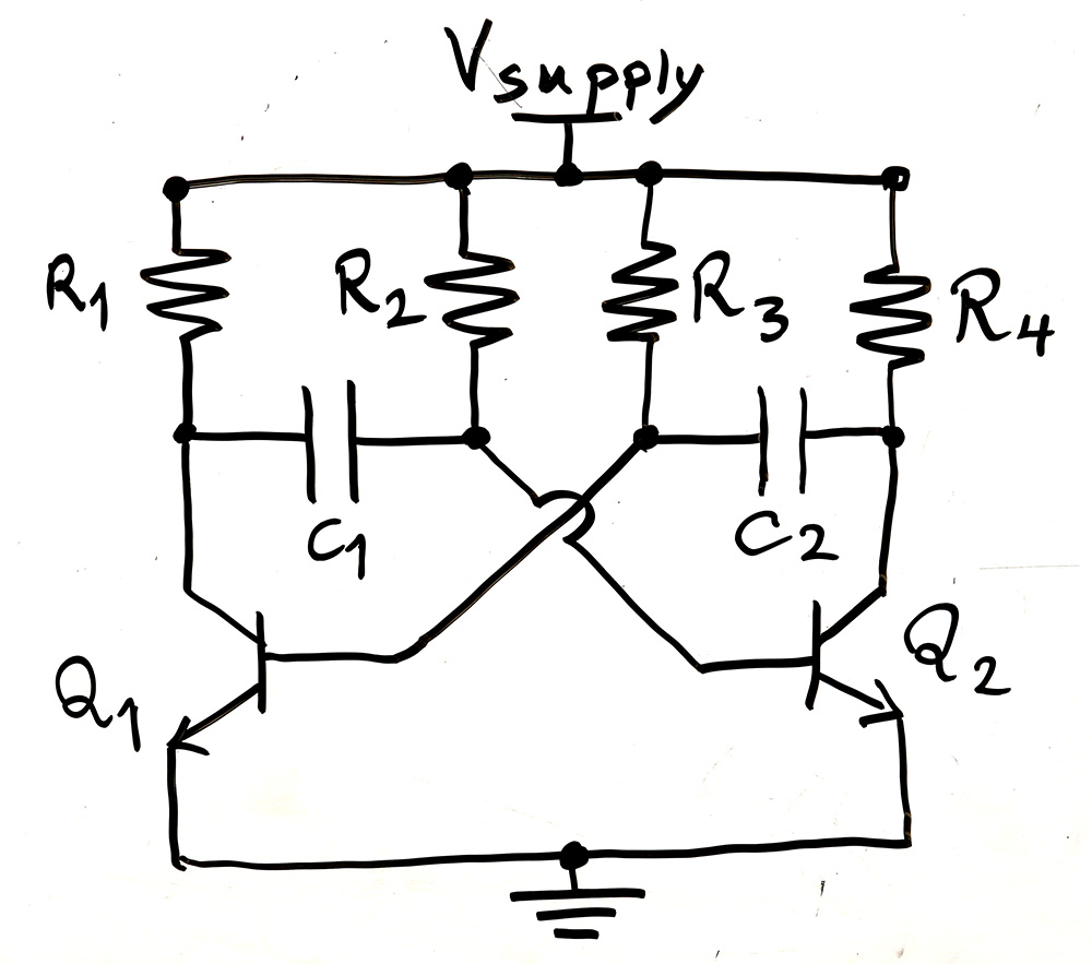
Now let’s explain the circuit I used. From what I found over the web, this specific circuit is credited to Vladimiro Mazzilli which as I explained in the video is a variation of the famous Astable Multi-Vibrator circuit shown below:
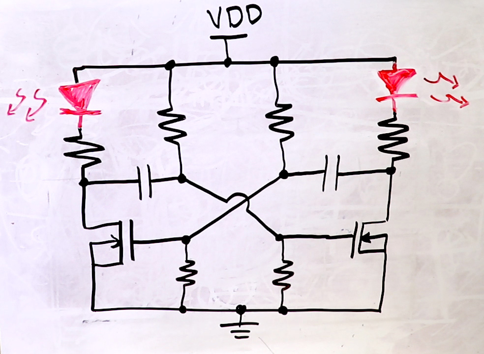
Of course the more famous vibrator circuit is done by BJT transistors shown below which works the same way. In both cases, the time it takes to charge the capacitors through the surrounding resistors defines the oscillating frequency. If you have different capacitors or resistor on each side, you can change the duty cycle.
Let’s focus on the ZVS circuit. It doesn’t take much for an inductor and a capacitor put together to oscillate! Just fling the circuit and it goes BOAOAOA! Well this circuit is not the final version I put together.
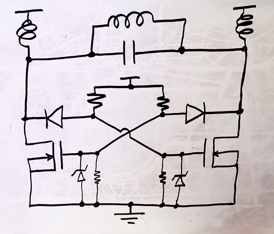
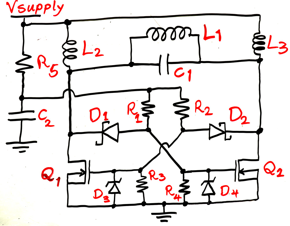
The circuit I put together looks more like the one below. Now if you can give me your time, I shall explain!!
STILL… I don’t like this circuit as is. See a major problem with this circuit is that the supply voltage must rise fast. Like I have to connect it to a battery directly or make sure my lab supply is on and then connect it. This is because otherwise if the supply voltage rises slowly, the kick to the LC circuit that makes it resonate won’t be great enough and the initial resonating voltages will be small and won’t switch transistors and dies away. In this case both gate voltages rise, turning both transistors on constantly and basically short the supply or battery and the result would be BURN!! So if for example you try to clean the supply voltage by a large capacitor, which I tried with bad results, the supply rises slowly and causes the same problem and circuit burns.
So, what was my criteria to design this circuit? First things first, I knew I would potentially need a ton of current when heating. You noticed in the video I drew over 17 amps. I picked a 12V supply so I could use my battery that could deliver more than my desk power supplies could.
Of course the other way to reduce current is to raise voltage, like they do with real induction cooker ovens. But then it is more challenging to design for higher voltages without… you know… getting shocked in every turn and potentially fail!!
So at 12V I decided to handle a few 100 watts, not to draw super huge amounts of currents either! Well my criteria is in my hands really, I’m the only customer, DEAL WITH IT!!
I thought the 20kHz the regular induction cookers use is a good compromise for this circuit. Higher frequencies could be better to reduce required inductance and capacitances for the same impedance as I mentioned, but that poses another problem:
The transistors in this circuit are not driven properly. YES I SAID IT! They are driven poorly. A MOSFET gate needs to be driven quite strong for super fast switching. That’s why there are MOSFET drivers that can handle 1A or above driving the MOSFET gate.
“But Mehdi, MOSFET Gate doesn’t draw current…”, go ahead and slap yourself across the face! MOSFET gate has an input capacitance, which means in order to change gate voltage you have to pour current into it to charge and discharge it and the more current, the faster the rate of change.
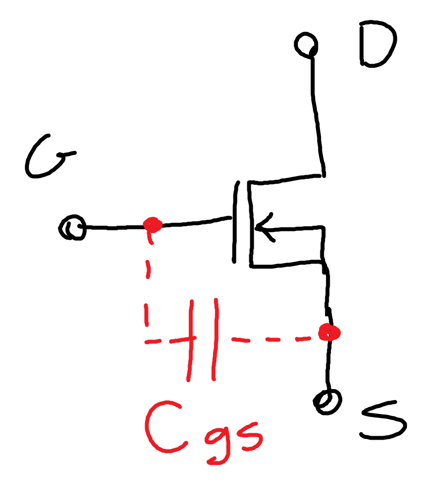
The main issue with powerful high current transistors is that they also have larger gate-source capacitances shown below (10nF in my case) and so need stronger drives.
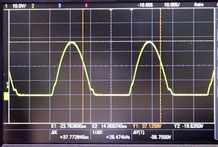
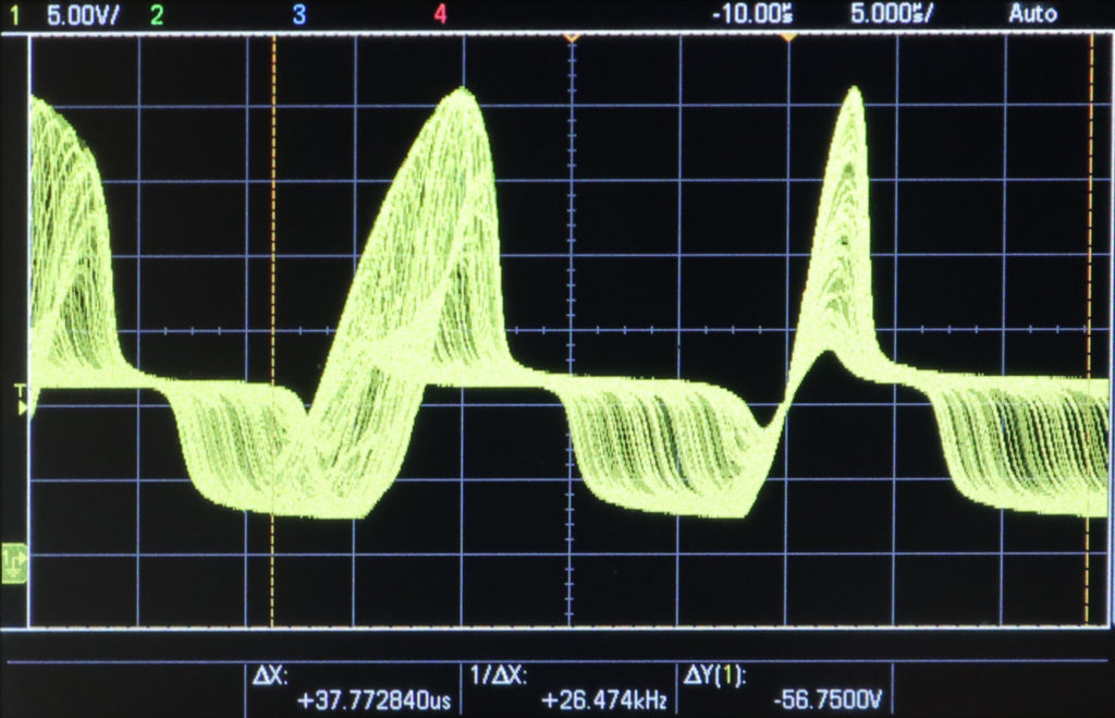
But in this circuit the gate is pulled up with resistors and lowered at the relatively slow pace of the oscillating sinewave shown below. You can clearly see where the MOSFET is switching in those flat areas at the lower voltages. Why do those flat areas happen? Read on!
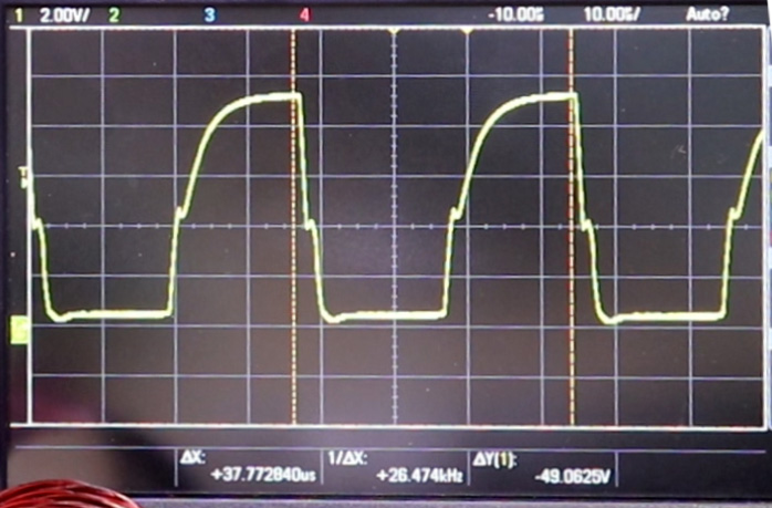
And below is the gate voltage. The rise time is dictated by the input capacitance of the MOSFET (Cgs) and the pull up resistor, which is not very fast, and the faster fall time is due to faster and stronger dropping resonance voltage showed above. But that’s not all, you see flat areas here too at around 4V that is the MOSFET VGS threshold voltage, which is due another internal transistor capacitances, namely drain-gate capacitance.
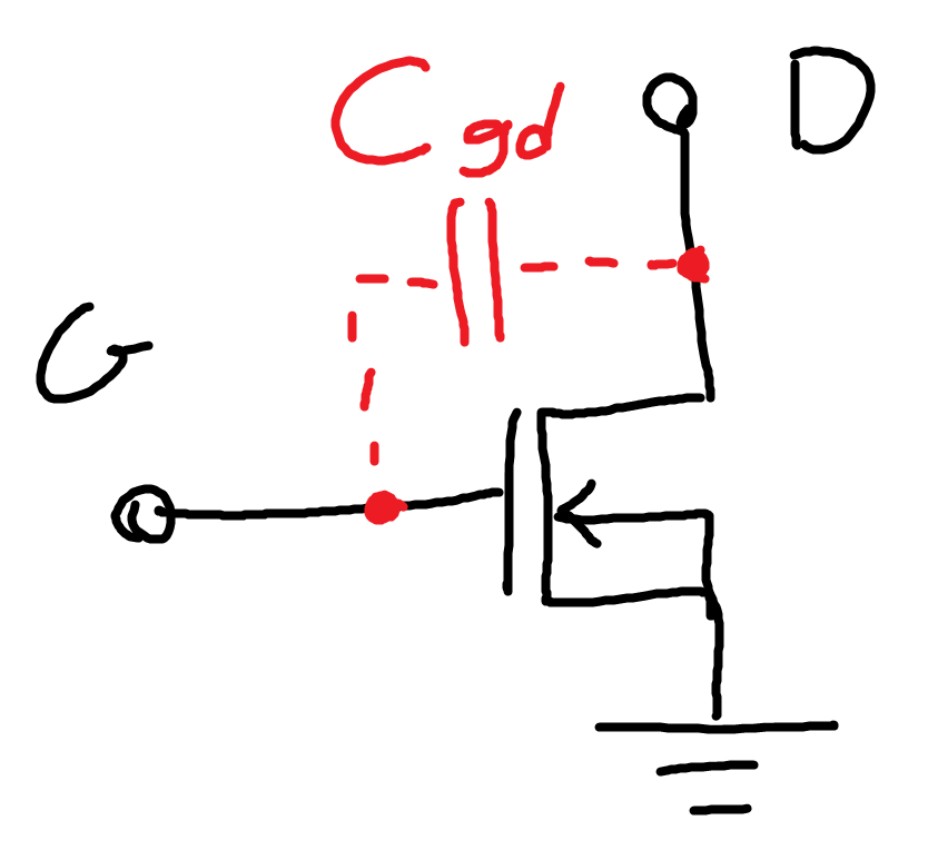
Below I show this internal capacitance as Cgd. When the drain of the transistor switches and the drain voltage changes rapidly, that fast change through Cgd creates a negative feedback to the gate and won’t allow the gate voltage to change easily as long as the drain voltage is switching, hence creating a flat voltage area around the threshold voltage when the transistor is switching and drain voltage is changing fast.
So the total switching time is greatly affected by both Cgs and Cgd. The slow switching speed means the transistor spends a relatively long time in transition period when the Drain-Source resistance is switching from a relative short circuit to open circuit. If the resistance is zero or infinite, for a limited voltages and currents there is no power wasted. But during switching with non-zero resistance, while the transistor is switching high currents too, large power is wasted over the transistor heating it up. That’s why transistor needs a proper gate drive to switch fast and shorten this transition period to lower power consumption, cooler transistors and higher efficiency.
In any case, a higher resonance frequency would also mean the switching period would be a larger portion of the cycle, wasting even more energy on transistors heating them much higher. 20KHz is a good frequency to keep power low. But any lower, you go into human hearing range and hear buzzing, not to mention inductors and capacitors must be bigger.
You might say, at least for pull up resistors, make them small to allow larger currents and reduce rise time. WELL I DID! They are 165 ohms now and still not fast enough. Remember when the transistor is off and gate voltage is low, those resistors fall between the 12V supply and get hot quick. Again, the proper way is a powerful gate driver, like MIC4452YN or similar.
And one more thing, the switching transistors put a massive noise on the power supply as you see in the picture below, especially at higher load current. Considering in the original circuit the gate pull-up resistors are connected to the supply, this noise would create a feedback to the gate causing unwanted oscillations, slowing down switching and other issues. That’s why in my circuit I added R5 and C2 to supply the pull up resistors, so that the voltage is filtered and clean during switching.
Now, D3 and D4 zener diodes are good to keep the gate voltage below a safe level. But since we picked the supply at 12V they should be save without. But then what if switching or other noises get into gate voltage and raise it for no good intentions? Let’s keep those zeners in! R3 and R4 are not necessary though, we have enough much stronger resistors there to pull gate around!
D1 and D2 need to be fast, so I picked some Schottky diodes.
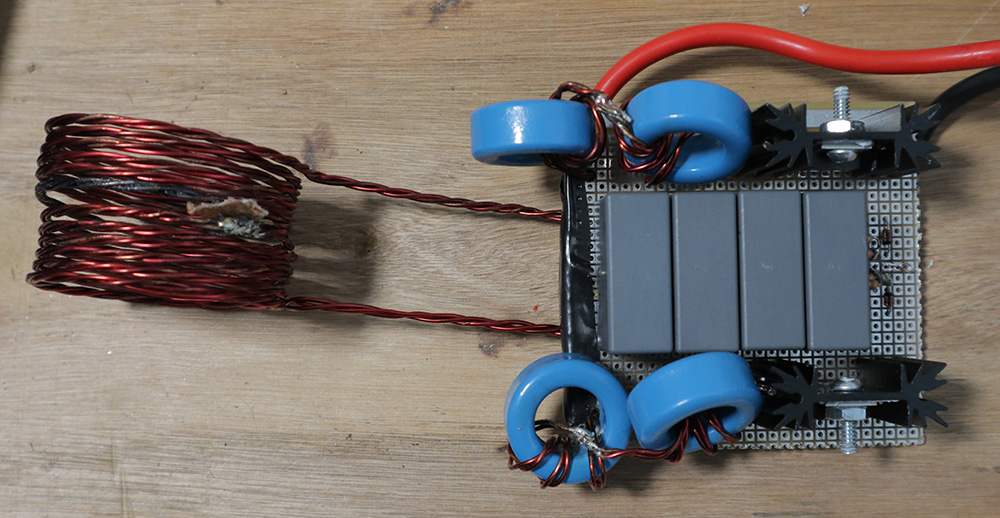
And for the massive 10uH inductor, WE NEED THICK WIRES! I didn’t have thick wires! I used some 18AWG magnet wire and made it three strands to handle more current and used an online calculator to design an inductor with air core:
https://www.allaboutcircuits.com/tools/coil-inductance-calculator/
Yet, L1 inductor is handling a ton of current, 30A peak or ~21A RMS in my case. And I measured my coil resistance is around 15mOhm, which means P = R x I^2 = 6.6 Watts is wasted over the coil itself heating it easily! That’s why having a fan to keep the circuit down is good and why my supply current is not zero at no load, lowering the efficiency. We need thicker wires, which would reduce unwanted waste and lower supply idle current.
For L2 and L3 I didn’t find something that could handle so high of a current and high enough inductance and maybe for good reason! So I decided to find a suitable inductor core and wind my own inductor! The core has AL = 10.8uH, which means one turn of wire creates 10.8uH. And Total inductance is AL x n^2, and n is the number of turns. So 4 turns would provide around 172uH. I used double wires to handle the current better.
But then I hit a problem. It seems my core get’s saturated easily at the currents I need. What does it mean to saturate? It means when there is too strong magnetic fields that fully magnetize the core, the core won’t be effective for more magnetic fields because it doesn’t magnetize any further. This means the core is weaker at higher currents and the inductance drops .
AND THAT’s the problem I observed. At no load when L2 and L3 currents were low I had 20kHz. But when I added some load, I noticed the frequency went up as high as 50kHz, AND the current from supply significantly rose. This was because reduced L2 and L3 that are paralleled with L1 reduced the total inductance and rose the resonance frequency, and couldn’t filter current effectively either.
So I ended up putting two of them in series for each inductor to keep the inductance high! I could reduce 4 turns to 3 on each core to lower the chance of saturation too. Anyway I ended up with this:
So, let me list you all the components I used:
- L1: 12 turns, ~5cm diameter and ~3.5cm length, air core
- L2 and L3 core: EPCOS/TDK B64290L0618X038
- C1, 4x capacitors in parallel: Kemet R76IR415050H3J
- C2: 10uF 16V Electrolytic
- R1 and R2: 165 Ohm 250mW
- R3 and R4 (if you use them): 10kOhm
- R5: 47 Ohm
- D1 and D2: On-Semi BZX79C15-T50R
- D3 and D4: On-Semi SB1100
- Q1 and Q2: Infineon IRFB7534PBF
- Heatsinks (use thermal grease): CUI Devices HSE-B20254-035H-02
And… there you have it! have fun!
Soft-Start Circuit
As I mentioned in my new video about making high voltage using this ZVS circuit, I added a simple circuit shown below to soft-start the ZVS.
It is not by any means a sufficient soft start, but at least with this circuit the main ZVS won’t turn on right away while the supply is rising slowly or fluctuating which could be pretty damaging to the ZVS. When ZVS turns on, it could draw double the amount of current through the LC circuit, which is already above 30A! Also if the supply rises slowly, the circuit may not oscillate at all, but will short circuit the power supply. So those early moments are very important.
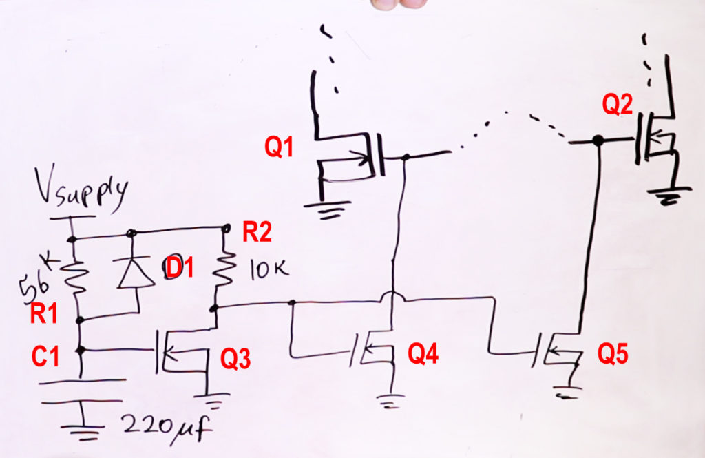
In the above circuit, Q1 and Q2 are the main ZVS transistors that oscillate at resonance of the main LC components. What I like to do is to keep them off for a few seconds after power up, and that’s where the rest of the circuit comes in. When Vsupply jumps up, C1 capacitor voltage initially remains at zero and charges slowly by R1. This keeps Q3 gate low keeping it off, and so its drain voltage is pulled up by R2 which is also Q4 and Q5 gate voltages. So, Q4 and Q5 are on, pulling Q1 and Q2 gate voltages down keeping them off.
As C1 is slowly charging through R1, eventually Q3 gate reaches the transistor threshold voltage turning Q3 on, pulling both Q4 and Q5 gates low turning them off, releasing Q1 and Q2 gates allowing them to start to oscillate.
What D1 does is kind of important. See, without D1 if you unplug the circuit, C1 voltage doesn’t drop quickly and if you plug it right back the soft start won’t work because C1 is already charged. But with D1 added, unplugging the circuit, as Vsupply drops rapidly under load, D1 will quickly pull C1 voltage down discharging it. So every time you plug the circuit in there is sure to be soft start function.
And of course adjusting R1 and C1 values you can choose the amount of on-time you like. The transistors I used for Q3, Q4 and Q5 are just some generic ones, 2N7000 or similar.
SIMPLE AS THAT!
jbi
R3 and R4 should be placed series with the gate of mosfets, or you should place two additional series resistor with gate path. In this picture: https://www.electroboom.com/wp-content/uploads/2020/10/final-circuit-2.jpg
high voltage flow acros D1 or D2 is tight to ground by Zener diodes D3 and D4.
Or i miss something, otherwise please explain.
Greetings from across the ocean 🙂
Hi Mehdi! What are D1, Q3, Q4, Q5 in softstarter? And what should I change, if i want to use it on 24V
Hi Mehdi,
I’m a biomedical eng and I am trying to put together a device of the sort for some tests. Can you please explain how you calculate the current passing through L1 or if there is a way to determine that by direct measurement? I need to measure the magnetic field it generates and I don’t have a Hall effect probe. Thanks!
add a multimeter in series with the inductor to measure the current
Can i use a 1uf polyester capacitor instead of C1?
Hi mehdi I’m a free energy believer and I believe you in every think you say because you test exept free energy you are making fake free energy devices not real free energy devices (as they made)
and I want you to wrap a long coil around neodymium magnets and test the output with a scope and please don’t make a fake free energy device
If you believe in free energy devices, you are in a bad way dude
yo creo q es posible Ya lo han conseguido No quieren q lo sepas.
There is nothing like free energy. Energy is either potential or kinetic. Energy comes from two or more bodies or matters reacting. In energy equation, output must be equal to input, if we ignore losses, errors or external influences.
Magnets do not do work, it is like how gravity does not do work. When you walk up a hill you are increasing your potential energy yourself and it is hard to move up. When you go down a hill, you are releasing the potential energy you added so it is easier. Magnets themselves cannot do work, so energy cannot be harvested from them magically. Read a physics book before making stupid claims
Hey Mehdi, I really enjoyed the video and your article 🙂
Could you by chance make your LTSpice file available? I’d love to play around with the simulation and mess with the component values for the ZVS driver.
Cheers!
Instead of the slow start, would charging up like a few milliF of capacitors first work, just before switching on another switch from that to power the ZWS? I tried, in my unknowing, to power it up slowly, indeed short circuiting, having me buy new mosfets.. so I thought why not power is up Fast…
Or use a car battery that is well capable of handling >50Amps
You can just put a switch instead
Meow
Can this soft-start circuit be used as a soft-stop/power off for LEDs? Currently Im designing LEDs taillights for my car, but the turn signals blink “faster” due to the instant shut down of the diodes after a power off, unlike the regular bulbs that fade for obvious reasons. Eventually I will have both left and right lights with LED and there will be no difference, but its still pretty obvious that they blink with a different rate. My idea is to put a circuit that extends the shut down time. Now that Im writing I think that this circuit is actually an overkill and capacitor will be better but I dont know how/where.
So apparently turn and hazard signal flasher units for vehicles that came stock with incandescent bulbs or other high current lamps use something called a thermal flasher. The frequency is deliberately raised when a low current/no current condition is detected, to inform the operator that the bulbs need changing. I guess that only works if you know about it. A quick search on the internet for 2 pin automotive flasher and you’ll find results for “LED Flasher” and “Thermal Flasher” alike. I have some confidence you could probably buy a drop-in replacement for your vehicles flasher unit if you didn’t want to roll your own 12V oscillator.
Kudos for the explanation! I’ve seen that original circuit diagram several times but you’re the first to redraw it in an understandable way and clearly explain how it works. Thanks Mehdi, I’ve learned something! Since you probably have some gate drivers laying around — would you mind adding them and show traces of the improved gate waveforms and their effect on the output?
I want to put this to my tesla coil, is it possible? i found out with a slayer exciter circuit that my coil resonates at @141kHz. Can the circuit deal with this frequency? also i have 30 windings on my chokes, is it a bad thing ? can they be the cause why i can’t get higher frequency ?
No, it cannot.
i would like a more elaborate answer if you would be so kind. Or recommend a schematic for a driver for my coil.
cool man
Can you make a handheld/battery powered version of this circuit please?
Hi Mehdi! Thank u for your nice work. Is this circuit could be built as frequency adjustable? I mean iron needs 40 kHz but aluminum needs 300 kHz for melting. Is it possible without losing power output?
A bit tricky, L and C values need to change and transistor needs to be able to switch that fast.
hi mehdi!! thanks for your efforts, i really appreciate.
what do u think about these ones? if this circuit is self oscilatting why we need driver ICs?
****://youtu.be/LfsJkvb4eao
IR2153
****://is.gd/BnJF1a
IR2153 ve UCC2720x
****://hackaday.io/project/162935-piernass-fast-zvs-mazzilli-driver
TPS2814P
how can we built balance between trigger pulse of IC for mosfet gates and resonant frequency of LC tank at the output side ?
your engineering point of view is fascinating and i need your sparkling ideas. thank u!
Hi Mehdi! Whats the input voltage range, output voltage range and output frequency range range of this circuit? Is frequency adjustable configuration possible?
I mean L value is constant but C values can be switched by relays (mechanically) or by mosfet switches (electrical way)
Comparing the list of components with the diagram, the diodes D1, D2 and D3, D4 are interchanged.
Greetings.
Hey mehdi, please tell me what to do if i want to add 3 igbts in parallell on each side. Also im concerned about the schottkey diode that is shorting the gates for switching purpose, what is it draws too much current? If i make a separate supply for igbts, it could burn the supply?
Hey Mehdi, try salvaging the components from the induction cooktop and making it failproof and high voltage at the same time.
Also if I am wrong, don’t put shitty comments under mine. I am a 12th grader. not a Doctor in electronics. Just correct me if I am wrong.
Just saying, could just try to remove the failsafe protection in the induction cooktop even.
Is the intention to make an induction heater, or to take apart an induction heater? He says at the beginning this isn’t a product[yet] if the product is something to cook with maybe that makes sense… if the product is something to melt metal with at home… It would probably need a very different set of fail-safes. In the induction furnace I used to melt steel at work we pumped water with antifreeze to keep the copper pipes, we used as the inductor, from melting. And we used aluminum oxides as both a container for the molten metal, and thermal insulator to prevent the high temperature liquid steel from melting the copper and flash boiling the water to steam and turning the whole contraption into a fragmentation grenade. I’m going to guess that the red hot steel was about 500° – 600° on the dog nose scale. No where near enough to melt copper, but considering all the smoke that was happening oils and other carbon chains were being oxidized first on the hot steel then the thinnest sections of insulation on the motor-wire and so on as the temperature rose.
I think the point was to give a simplified explanation of how the circuit works along with a healthy respect for how dangerous it can be if you luck around too much with things you don’t understand and crap out before you get the chance to.
Mehdi, I’ve been a fan of the show for a while and I think some links to your own videos to explain terms and concepts you hand waved away with words like series, parallel, reactance, current, voltage, and so on would be really helpful to someone who just jumped in and wants to learn but feels overwhelmed like sanee aman in the comments further down the page. You did a great job explaining the missing capacitor in the mos-fet above, and the missing transformer in professor Lewin’s example circuit, in your video on Kirchhoff’s Voltage Law. Similarly, some discussion of the missing reactance and resistance from the battery and power supply, along with a little about impedance matching, resonance, phase angle, and power factor would shed some light on the issues at play(and maybe a little bit about how to make better[not better… more accurate] spice models).
When I was learning electronics in school we would have stick-figures of “Timmy” in our circuits from time to time and we would have to identify if Timmy was safe, shocked, burned, or dead before we could do our labs. It was kind of important since there was a potential between two of the metal enclosed chassis grounds of neighboring lab benches. The potential was high enough to be annoying if you understood the warning and bridged them with your body accidentally anyway, but low enough to still be funny, and educational. From time to time I’ve been called upon to explain electrical concepts to people and so far I’ve continued to use Timmy in my models when I felt it was appropriate. Mehdi you are far more animated and memorable than Timmy could ever hope to be, and I would love your permission to put “Mehdi” in the circuit for future people I would hesitate to call students for fear of being saddled with the responsibility of being called teacher; but you’re not Kenny and I don’t think you need to die or even traumatize yourself in every episode.
I had a question. Can the circuit drive the transformers for a Inverter? they too run on high frequencies , and if so would make driving it easier then trying to make a Fet driver circuit to drive the mosfets that then drive the transformer.
Pingback: Making Induction Heater with ZVS Circuit – Roger.Party
Hey Mehdi! could you maybe put a fails vid up on your next post? I’m a big fan!
watch the fails on youtube. his website is for people who want to actually learn.
I’m not allowed on YouTube. I’m a kid. So leave me alone. Don’t be one of those people that mouths off to kids.
And I do want to learn. But I’m a kid, and I can’t MESS AROUND WITH ELECTRICITY!
Classic!:)
If you can watch the videos here on this page, you’re already breaking the rules because the video’s on this page are youtube videos. So you either have to discontinue using this site, OR you can open your browser console and add an iframe that points back to his youtube channel to the document of your page(since that’s all an embedded video is anyway)… If you don’t have a link to his channel page you can edit the url (src) in one of the existing embedded videos by removing the part that says “embed/” and replacing it with “watch?v=”. You might want to make it display wider and taller, by adjusting the width and height values. Immediately after you update the src attribute of the iframe it will load the standard youtube page for that video. Below the video you will find a link to his channel next to his portrait where you find his channel name, you can then right click on his channel name and copy the link, or you can click through and open his channel page and get the url with javascript by reading the contentWindow.location.href of the frame.
Just connect the flyback transformer and voalah
lmao looks like i need 2 more years of education to understand.
Wait it got so hot orange this is like an electrical forge.
That’s exactly what incuction heating is 😀
Forging uses impact to heat and deform the metal…
Back to the website,
You’re my hero!
You can maybe use a push-pull configuration to drive the mosfet.
Thanks a lot for the article ! Nice job !
great scott has already made this type of circuit
griit scitt his ilriidi midi this tipi if circiit
bruh
Yrah, he did. With no explanation of the circuit. Useless…
Great Scott video was called “How does Induction Heating Work? || DIY Induction Heater Circuit” he explained how the induction heating worked in various metals. It’s only a 6 minute video and it’s full of very useful information for someone who’s interested in the subject. Mehdi’s video doesn’t cover every last in and out of the circuit either, it doesn’t make it useless. they’re both awesome video’s but for different reasons.
Great Scott was pretty clear that he thought his viewers wanted to see him heat up metal and burn/cut stuff with it…
Mehdi said something about this not being a product “yet” I wonder where he’s going with it. Intrigue is good… but so are answers.