As per Ray William Johnson’s Request, here I make an electric toothbrush:
Yeah, it’s not the best idea to make an electric toothbrush out of a frother, but I guess in the hours of desperation where you are in real need of an electric toothbrush to brush your teeth, and at the same time you don’t give a SH#^% about the health of your gums, you can use this method!
By the way, drop me a line if you are interested in purchasing the control circuit in form of a kit you would assemble, or an already assembled unit. I want to see if there are enough people interested in purchasing the circuit for me to put the effort into creating a package.
On the other hand, controlling a DC motor speed is something that can come in quite handy and is pretty much used everywhere.
Like I mentioned in the video, to control the speed of such a motor they use PWM, or pulse width modulation. Imagine instead of turning the motor continuously on, you turn it on an off quickly. The frequency of turning the motor on/off would be so fast that the motor would not completely turn on or off, but it would rotate at a speed that is proportional to the on-time in every period.
Now by adjusting the pulse width of the on-time in every period you can adjust the speed. And this is basically pulse width modulation.
The circuit below is what I have designed to do the PWM control of the motor:
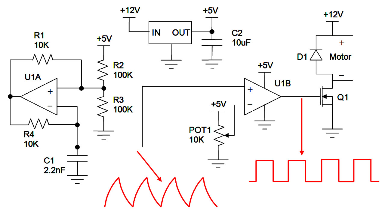
PWM control for tuning DC motor speed
There is a 5V regulator on the top center of the schematic that generates a fixed voltage. A fixed supply voltage is important to protect the control circuit, as well as keeping the circuit functionality consistent.
U1A circuit is an oscillator. The output at the capacitor is formed like a sawtooth wave. If you need a square wave instead for another application, you can use U1A output. The frequency of oscillation is tunes mainly by C1 and R4, but is also dependent on the threshold voltages the combination of R1, R2 and R3 generate when U1A output is high or low. For this circuit the frequency is roughly around 7kHz.
Sometimes the PWM frequency is adjusted to above the human hearing range to avoid creating an audible annoying tone.
U1B is a simple comparator that compares the potentiometer POT1 voltage level to the sawtooth wave and creates a square wave signal with a fixed frequency, but with a duty cycle dependent on the position of the potentiometer.
Duty cycle is the percentage of on-time over one period.
Following image shows the potentiometer level changing on the sawtooth wave and how comparing the two creates a PWM signal.
PWM Signal generated by comparing a sawtooth wave with a DC level
And finally, transistor Q1 acts like a switch that turns on and off by the PWM signal and turns the motor on and off. Diode D1 has a very important role of preventing over voltage and damaging the transistor. You know, the motor is basically an inductor and when the switch is closed, it charges to some current, and when the switch opens, it wants to continue discharging its current. But as the switch is on, the inductor can’t discharge its current and instead its voltage spikes very high. But with D1 present, the motor has a path through the diode to discharge its current and the voltage of the motor at the transistor side will not exceed the supply voltage plus a diode drop.
Please put me out of my misery: what mosfet can i use WITHOUT any driver?
use any just put a 10k resistor between source and gate
hi,
Could you give a formula about the calculation of frequency and Vp-p of the triangular wave?
this comment section is toxic
Pingback: 会唱歌的闪电——特斯拉线圈 - 完整
hi am very interested in your product cause i will like to make it a corporation i think we can be business partners or you can be a supplier to my corporation how about that
lol
hi am very interested in your stuff can you prepare the package for me cause am planning to make it a coporation so we could be patrners what do you say
fuck u madi
u dum d 7um
go out man
Would the output of U1A op amp actually be generating a square wave? Would it be possible to use just that to generate a fixed pwm instead of adding the comparator generating the square wave from a sawtooth?
It IS a square-wave generator but he only plot the positive half of the wave and it is only positive, there is no the negative half of the wave.
Forgot to ask, Can I use the PWM controller for a boost/bucket converter to do the switching.
Yes, but you would probably need to use a microcontroller to regulate the duty cycle, otherwise the voltage would drop when you drew current.
Mehdi, Can you provide me the part numbers you used for designing the controller? I looking to design a high frequency PWM controller. Can you advice me on how to go about it. I don’t want to use any commercial chips ( pre made PWM ICs). I love your videos.. keep it up
I enjoy your videos. I was looking for a simple PWM circuit to test fans. This circuit is much simpler than most, lot’s of them had diodes and timers and multiple ICs to do the same thing.
i love this circuit it works really well for what it is but i think you should just say in the article that you need a logic level mosfet cuz most of the standard ones wont turn on fully with 5v on the gate. thanks for the circuit!
Hi Mehdi,
You sad that the frequency of U1A circuit is dependent on C1 and R4.
For my understanding,do you mean the R4 limits the current and the C1 determines how much it well charge. Together they control the period of the circuits.
They work together, R4 charges and discharges C1 and the charge rate is with a time constant of R4 x C1. The bigger they are the slower the charge time and so the slower the frequency.
Pingback: Music, Magic and Mayhem with Tesla Coil | ElectroBoom
Im looking to buy a dc motor thats already assembled how much will it cost?
hi im 100% new to this, i want to build a micro quadcopter for a school science project and so far im stuck at esc as in zimbabwe a lot of things are not readily available, so i thought of building my own to control 4 salvaged dvd motors. i need a detailed component list and circuit diagrams
Well… good luck!
Did you make it?
can I use a LT1366 as my U1A and U1B because I want to stick to a 8 pin dip ic
There shouldn’t be a problem.
Hi, I have a few question
Is it possible to make multiple PWM output (U1B) with a single oscillator (U1A)? What change need to be made?
Also when you design some circuit, did you just create the circuit then test it out or simulating it on software first?
Hi Irfan. Not sure what you mean with multiple PWMs. But the PWM duty cycle can change by adjusting POT1.
Depends, with these circuit here I’m so sure of how they work I just make them and they work.
But with new ones, I design it first, then simulate them and then make them. If they don’t work I will troubleshoot them.
Hi Mehdi, thanks a lot for this circuit. I have some question. first, can you give me details about U1A and U1B? second, Can I use this circuit for higher frequencies such as 1MHz or more? And last but not the least, is the out put and the input synchronized and if yes what is the time delay between them? Thanks and Im waiting for your response.
Best regards.
Davoud
Hi Davoud,
For U1A and U1B any comparator with push-pull output would do. But it also depends on the frequency you need. If you need faster, you need faster comparator. I am running over 1MHz on my tesla coil driver with the same circuit. If you search a bit you will find comparators with small rise/fall time and delay.
Again the time delay between them would depend on the comparator speed. BUtu of course I/O are in sync.
Have fun!
thanks a lot. i am gonna simulate that tomorrow.
hey man, i want to make a simple circuit to control a dc motor (from an old dvd-rom). What do i have to use for voltage regulator? is it something i can find at a store? I live in greece by the way so i want a clean explanation.
Thank you your videos are fantastic i am a subscriber keep up the good work
Why don’t you just use a wall adapter that converts to the voltage you need? Like 5V or 9V? I’m not sure what voltage your motor is rated for, but starting from 5V wouldn’t hurt. You could also use regulators like 7805 for 5V or 7809 for 9V
hi my motor is 12dc. Actually i want to control 2 motors, but that’s not a problem i will just use a transformer with 2 secondary couplings (i hope i say it write) and do 2 separate circuits. Thanks for help, i use the Proteus Isis program for simulation when i find time to try it i will inform probably
So, you want to use dc supply to your motor? Does it works, using dc supply to a transformer?
Hi,
How can I get the amplitude of sawtooth wave output? This output will compare with the POT1 voltage so that its amplitude should be 5V right? But I don’t think that oscillator can output a 5v sawtooth wave. I’d like to know where I was wrong.
You don’t need 5V peak to peak. Your potentiometer voltage can cover what ever range it is for 0 to 100%. If you go beyond max and mean, it simply stays at 0% or 100%.
Oh, I understand. It’s very clever and even more useful than my course. Thank you for your answer.
By the way, do you have other contact information like email? Maybe I can consult some questions more convenient. 🙂
I hope you don’t have adult rated questions! My email in under the About tab.
Mehdi , next year ill study electronics and electric circuits
for gods sake make few videos explaining basics and few tutorials
with ur sarcasm and “bloody god save me from it” humor i think ull help a lot of students.
p.s make another video soon, watchin the same videos over and over again makes me wanna eat an apple.
🙂 I’ll think of something! And eating apple is good too!
mister,i know apples are good.
problem is i dont have any o.o
Hi Mehdi, I am interested in electronics and I wonder how does that sawtooth wave generator work and what happens when I change the value of capacitor (2.2nF) or resistors?
Can I use LM358 for U1A and U1B? Also I think that it will enough to use one oscillator circuit and three comparator circuits for controlling 3 motors, right?
That sawtooth generator is basically called a Schmitt trigger oscillator circuit. The output of the comparator is either high or low, like a digital signal. Depending on its state, it sets the positive input voltage of the comparator which creates two threshold voltages. So it output is high, C1 gets charged through R4 to rich the higher threshold. When it gets there the output drops low and the threshold goes low and the capacitor starts discharging to the lower threshold. When it passes the threshold, the output jumps up again.
combination of R4 and C1 changes the time constant which effects the frequency. Also R1, R2 and R3 change the voltage thresholds and also effect the frequency.
LM358 is not a rail to rail OpAmp and so your voltages will be limited and depending on your components the circuit may not work. Find a rail to rail input and output OpAmp.
I’ve made this today with LMV324 and 7805 as regulator and used BC337 as transistor. When I plugged 12V adapter and tried it on a low power motor, it worked for a few second then gone 🙂 I don’t think current damaged the circuit but some smoke released from card. Do you have any suggestions?
Can’t tell from this far, but you used a BJT instead of a FET for Q1. Did you put a resistor on the base to limit the base current? If not that maybe the reason. base-emitter is a diode and its voltage can’t go much above 0.7V.
I’m having a hard time choosing between mechanical and electrical engineering. Can you sell me one as unbiased as possible? 🙂
They are both good in my opinion. It very much depends on your preference. There is a new program nowadays called mechatronics that is a combination of both. So you learn both together to some extent. Then halfway you may decide you like electronics more or mechanics more, and take more courses towards that. And either way, you learn a good deal about the other one too.
I made fucking bomb…
would it be ok to use a 5.7k pot? or do I have to use a 10k?
Yes that’s fine. The value of potentiometer will not effect the circuit performance, unless it is so small it can short the supply.
THANKS
how do yhu maik itt?
Hi,
I am really interested in the DC motor speed control package. Do you happen to have any packages available? If not could you send possibly send the part numbers of all your components so I could build it myself?
Thanks,
Rob
Sorry, I don’t have any. I wanted to see if the interest was high enough, I would prepare a package. But the number of interested people are very few. Thanks for the interest.
Hey, I’m interesting in buying a package for the Dc Speed control circuit.
hey do you have a list of what parts you used in this project?
i am new to this and realy intrested to try this, what kind of mosfet did you use
and what is u1a and u1b?
thanks in advance
Use LMV324 or LMV358 for U1, they are the same, just different number of OpAmps in one package.
I would buy a few if you make it possible to vary the frequency too!
You might be able to control it to a certain degree by replacing R4 with a potentiometer. Not sure how much variance in the frequency it would allow though.
You should make a cell phone frequency jammer!!!
Nice one nice one please make more videos please you are awseoum
Taking a good care while buying an Electric Toothbrush is must as that will effect our oral health.
Id buy one.
Yes, I’ll buy two!