How to Make a Taser (Stun Gun)


Turns out it is quite easy to make a taser, here’s how:


Well, again don’t zap anyone with this. You can make other useful devices with this design such as ignitor, a noisy-sparky-dim-inefficient light bulb, scary Halloween costume, or whatever you can imagine! Just don’t hurt each other.

So like mentioned in the video you can use a transformer to create very high voltage. Creating very high voltage without a transformer can be very hard, because you would need very high voltage rated components on the output (>10000V), while with a transformer you can pick lower voltage rating components on the low voltage side and let the transformer take care of creating the high voltage. But how does a transformer work?

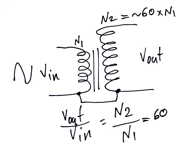
I make it simple here: a typical transformer is made of two wire windings around the same core (air, metal, ferrite, etc.). When you apply AC voltage on one side, you create magnetic field which passes through both windings. Now changes in magnetic field will move electrons on the secondary and hence create current flow. You need change in magnetic field to move electrons back and forth, and so transformers only work with alternating signals. They don’t need to be sine wave, but changing in general.

Now in an ideal transformer the output to input voltage ratio is equal to output winding to input winding number of turns, like I showed in the picture below (60 if for my specific transformer).

Ignition Coil Winding

Ignition Coil Winding

On the other hand, the output to input current ratio it proportional to input winding number of turns to the output, which is backwards the voltage ratio. As you know power is voltage times current and if you combine these together you will realize that in an ideal transformer (100% efficient) the input power is equal to output power. Of course in real life there are many losses that will reduce the efficiency such as core losses in form of heat, wire resistive losses, etc…

Like shown in the figure above in a car ignition coil one side of the primary and secondary windings is tied together, which doesn’t change the behavior of the transformer. It reduces the number of connections to the coil, but also eliminates the primary to secondary isolation that is not needed here, but is critical in many other applications such as isolated power converters.

So like a regular transformer, if I put 10VAC on the primary of this specific transformer with 60:1 secondary to primary winding ratio, I will get close to 600VAC. But for a taser I need over 10000V on the output and that’s why I use a useful behavior of the inductor.

Unlike a capacitor that tried as hard as it can to keep the voltage across if as stable as possible by sourcing and sinking surges of current, the inductor tries to keep its current stable as much as it can, by surging the voltage across it. So if you charge it to a certain current, it tries to not allow or slowly change the current. What does that do for us? Take a look at the circuit below. At the beginning the current through the inductor L1 is zero. When we close the switch, the inductor slowly allows the current to rise through V+ supply. Say it rises to 1A and then we open the switch. But the inductor wants to continue driving 1A current. So what happens is that it pushed the current through D1, which was off up to this point and turns it on, and the current runs through R1 resistor. Now let’s say R1 is 1kOhm. So 1A x 1k = 1000V is generated across the resistor in form of a spike that dissipates quickly. So just that easily, we created 1kV spike. This means that the voltage across the inductor on the diode side jumped close to 1000V, all in order to continue outputting 1A.Booster Circuit
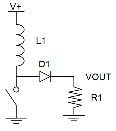
This circuit is the basic concept behind the voltage booster circuits. Just be aware that if you generate huge voltages, all your components such as the inductor, switch, diode and resistor should be able to handle and not break under such voltages.


Now the primary of the transformer is the same as an inductor, it has self inductance. If we charge it and let go like I mentioned, the voltage would spike up and that converts to even higher voltage on the secondary. My specific car ignition coil has a 0.7Ohm primary winding resistance. So if I put 12V across it, I would have 17A through hit. That is beyond my supply and battery limit and so pulls their voltages down to a lower level which is still OK. For example with the power supply, I can’t run more than 10A.

When I disconnect the supply, I see spark on the primary too because the 10A current tries to keep going and creates a high voltage arc, but also the secondary voltage rises and makes an arc, especially when I add the capacitor. So like I showed in figure below, the self inductance of primary and the added capacitor are charged together when switch closes, and then start oscillating when switch opens, creating a high voltage oscillating waveform.

Oscillating Circuit
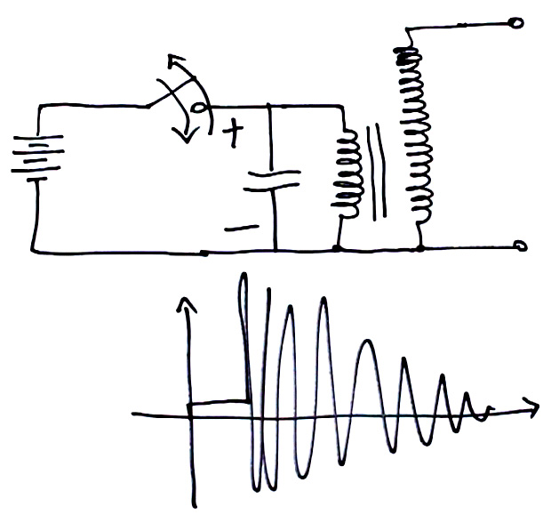
The reason for oscillation is that when the switch opens, the inductor wants to continue giving out current, the same direction that capacitor wants to discharge its current. So the current of the inductor keeps flowing happily until the capacitor completely pours its charge into the inductor. So the inductor has energy to continue and it starts charging the capacitor in the opposite polarity and charges it all the way up to a negative high voltage until it doesn’t have any more energy to give. But now the capacitor is fully charged and starts depleting it energy into the inductor running current in the opposite direction. This oscillating cycle would continue for ever if it wasn’t for the losses in the circuit such as resistances that would cause the voltage level to drop.

Also this oscillation creates even higher voltage on the secondary that as we saw creates very high voltage sparks. From the gap the sparks were arcing over, I would say their voltage was over 20,000V.

And so I created the circuit below to create a continuously arcing circuit. The way I designed this circuit, when you press SW1, you actually connect 12V across the relay coil through the relay normally closed contact. This will cause the relay to switch away, which removes the voltage across its coil and turns it off, and so relay returns to normally closed position, and hence relay will oscillate. The capacitor and resistor across the relay coil are to slow down the relay switching frequency. This is to allow the 12V to be across the transformer primary for a longer time so that it charges high enough. And when the relay switches away, we have a spark on the output. There will be sparks like a taser as long as we hold the switch.

Continuously Arcing Circuit
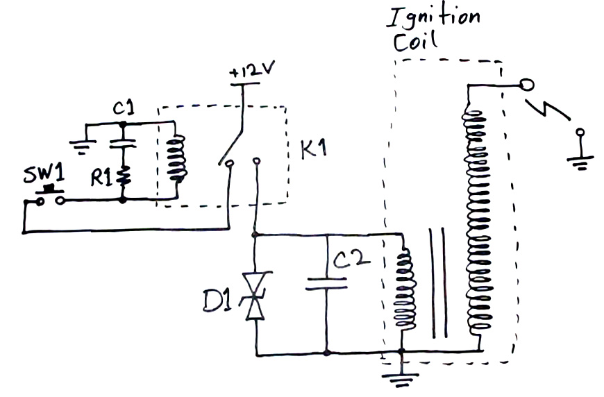
I chose C2 capacitors as 250V rating to make sure they won’t break easily, and also diode D1 clamps the primary voltage around 350V. C2 is made of 10x 1uF capacitors in parallel. Here’s a list of my components:

  • SW1: regular push button
  • C1: 22uF >16V aluminum capacitor (mind the polarity)
  • R1: 4.7 Ohm (current limiting and timing)
  • K1 relay: Omron G8QN-1C4 DC12
  • D1 TVS: LittelFuse SMAJ350CA
  • C2: 10x 1uF 250V ceramic capacitors in parallel
  • Transformer: car ignition coil, get it from any car auto part shop

This is not the most awesome circuit, but maybe it is the easiest one to make. There are things to consider here:

  • When the relay disconnects, the transformer creates strong sparks on primary too to get rid of its charge. Those sparks can eventually hurt the relay by welding the relay contacts together. That kept happening to my relay too and I had to kick it to disconnect the relay contacts.
  • D1 rating I used was above C2 rating, which is not the best thing to do. I couldn’t find small size, large value but high voltage capacitors so I had to go with 250V. At the same time I wanted higher voltage on primary to create bigger sparks. So D1 rating was at 350V. My capacitors didn’t break. But going like this would reduce their lifetime.
  • This circuit can also be designed with silicon parts like transistors (IGBT or MOSFET) but it would need more circuit, like an oscillator and driver which would make the circuit more complicated. I like simple and quick, sometimes!

Make sure you don’t get zapped and make your own.


312 thoughts on “How to Make a Taser (Stun Gun)

  1. Medhi,
    How about designing a version that’s driven by an oscillator instead of the relay?
    Did you ever consider selling kits of your designs?
    Great channel!
    Mike

  2. THIS IS AN SOS FOR MEDHI, PLEASE HELP. Dear Medhi, I’ve been trying to replicate this circuit and I need some serious help because my problems go beyond logic !! I’ve built the exact same circuit with parts of identical values, the only difference being the transformer (which is a 220 V to 9 V transformer wired in reverse for stepping voltage up). When I test the circuit WITHOUT the capacitors, I get tiny sparks at the secondary (so far so good). However, when I test the circuit WITH the capacitors, there are no sparks anymore. This doesn’t make any sense… Do you have any suggestions ? Thanks a lot !

    • Maybe it is the question of oscillation frequency on the primary LC circuit. I would try some other capacitor values.

    • your secondary now is the 220V side, it is not build for 10000V so it sparka over, internally between the windings, destroying the coating of the windings.
      you need a special transformer that can handle the high voltages.

  3. Hello sir, can you please give me the connection wiring diagram of this circuit. Sir i need this diagram urgently. Please help me. You can send me the wiring diagram at my mail id: (surajaverma786@gmail.com). Love from india

  4. If I want to use 6V ignition coil from motorbike, should I do something different?

    • Use a six volt relay and supply.
      If you cannot then I have a circuit for you which can work.

    • C1: 22uF >16V aluminum capacitor

      C2: 10x 1uF 250V ceramic capacitors in parallel

  5. Hello!!! Big fan here

    I wanted to know if this is usefull for the following project.
    I want to create a pulse generator, but i need high voltage (2-3kV)and low current. I am thinking, instead of using that button, to use LM555 timer, for pulse control, and use like a motorcycle coil, not a car coil, for less voltage. Would i be able to do it?

  6. Medhi (sorry if I butchered your name)…. I need some help.. please please please continue the electronics basics series, I need a teacher!!!!!!! You are the one!!!! Can you please make a tutorial on how to do this same thing using mosfets or transistors… I have a general idea but need some guidance so… THANK YOU!!

    • It’s EZ, you need a PWM signal generator to feed it on the base for the gates to open and close as fast as possible.
      You can use a microcontroler to generate the PWM signal.

    • It looks like u comprehend English, then what’s wrong with u reading a book πŸ™‚

      • Why does his comprehension of the English language mean he can read a book?
        Last time I looked, books were written in almost every language that has a written form.

        555 for PWM
        MOSFET as the switch.

  7. Please, I did everything but my ceramic capacitors were different and I didnt have that TVS diode. What I need to do to make my work. I got pretty big collection of common parts from many electronics

    • I think you could dc, because the build in oscilator.(the thing he described using a spring:)

  8. Hi Mehdi! Is it possible for me to just use the primary side circuit/not use transformer and increase the resistance of R1 so there will be high voltage sparks? I do have small transformers but they have low turn ratio and not good enough isolation..

    • No, You need current to pass through, increasing resistance would reduce it significantly.

    • R1 is a timing resistor to tune the frequency of the relay oscillator. Use a potentiometer to change the resistance during run time. Then mark potentiometer point where the sparks jump the highest distance. It’s better to find the resonance frequency of the ignition coil’s primary inductance and the parallel capacitor(s) and then choose the relay frequency accordingly.

  9. Hi Mehdi! Is it possible for me to just use the primary side circuit/not use transformer and increase the resistance of R1 so there will be high voltage sparks? I do have small transformers but they have low turn ratio and not good enough isolation.

  10. Hi Mehdi.

    I really enjoy your work. Fun and very informative.

    I’m curious if you could use a motor run cap for C2? Something like this: “Podoy CBB61 Fan Capacitor 12uF 250VAC 50/60Hz Black Metallized Polypropylene Capacitor” (Amazon). This Amazon page includes links to an 8uF and 10uF options as well.

    Keep up the good work – and please don’t seriously hurt yourself!

    Thanks!

  11. Hey medhi I need your help !

    is it ok whn I use a Omron G6A-274P-ST-US 12 VDC ? because the one you get in it I cant buy so easily… or I have to wait for it… along time :/

    and the resistor current and time limiting ? which would be good for it ?

    would be great if you or someone could respond !

    • Just get any 12v 5pin relay that is capable of at least 10 amps. I need to know where you live so I could give you a link of the relay.

      The current and timing resistor is not necessary because I made the same thing without it and is working flawlessly.
      Mostly these relays have coil resistances of around 400Ξ©.

  12. Hello Mehdi,
    I like your page and videos very much.
    Seems you have a very strong emotional binding to electricity.
    Charging and discharging the own body with electrons gives always best feeling and respect to the job of Electrical Engineers…….it is a “must” to feel what energy is – before talking about ….. so I am el. engineer too …..
    But – is there a doctor or hospital very near you, when you make your self-tests with high voltage ?

  13. How does the spark jump over to electroboom when he moves his the ruler closer. As i understand the current has to flow back to source and how does he complete the circuit in that case?

    • he is holding a switch and switch is connected to a coil in relay and coil is connected to ground as well as secondary of the transformer.

      • Hi,I’m wondering what is the switch made of? Did he just shorts a wire with his bare hand? If so, then I agree with your relpy. But if he used a button and press it, will he be stunned too? In my opinion a button’s surface is made of plastic, when he pressed it, he won’t make a circuit for the electricity to go. So maybe he won’t be stunned. Thanks!

        • I believe It’s not because he is touching the switch, but actually because of the slight capacitance of the human body. We always have a slight capacitance to ground, and therefore AC current can couple through us. It’s the same reason that you can get shocked by touching a live wire even when you seemingly aren’t completing a circuit.
          When Mehdi places his finger close enough to the spark gap, he eventually presents a better path to ground through his body capacitance and the current flows through him instead.

          I suppose it’s also possible that he was touching the exposed solder joints on the switch, if you check the video it looks like his fingers were pretty close to them.

          Anyway, hope this helps.

  14. Hi blogger, do you monetize your site ? There is easy way to earn extra money every day, just search on youtube
    : How to earn $25/hour selling articles

  15. Mehdi doyou think i can use other types of capacitors instead of blue ceramic?

  16. I found what I believe to be a homemade taser. My dad built 30+ years ago i im trying to figure out how the thing works so i can resodder the many broken connections and get it working. Howerer im more confused now than before. Because it runs off or 6 1.5 v dc and so guess that doesnt go directly to what I assume to be a transformed out of god knows what. But I am makimg progress i know the led indicator light works. Thats a win in my book

    • Jarod,

      If it runs off DC then he must have used some sort of switching circuit. You could do it with a 555 timer turning on an SCR that was connected to the coil primary. Using two such circuits I believe would produce an AC type signal. I would think it would also be easy to tune by a simple resistor adjustment.

  17. Medhi, what specific car ignition coil did you use? So I can get a circuit close to what you have. πŸ˜€

    • Differrent models of coils behave quite identically across the range that is available out there. Generally, they tend to have a DC resistance of approximately 1 ohm across the primary winding and a resistance across the secondary in the order of several kilo ohms. The ratio of turns vary, but typically falls within the range of 1 to 50 and 1 to 200.
      The coils would be constructed around ferrite cores and submerged in oil to handle the high voltage.
      The major discrepency that you may have to deal with lies in the coil of the relay. Different relay solenoids may have different characteristics(e.g. resistance, shutoff voltage and current) which may demand a bit of trial and error with C1 and R1 to find the sweet spot where the capacitor C1 provides the solenoid with JUST ENOUGH residual post-cutoff current to sustain the magnetic field whilst the switch arm swings away from the normally closed contact, enabling it to reach the normally open contact to energize the primary of the transformer; and not TOO MUCH so that the frequency of the oscillation is significantly reduced to a point where the full potential of the transformer is not utilized. (sorry for the long sentence)
      Initially when I set out building the circuit I fathomed that I could work out all parameters by theoretic calculation based on the inductance, resistance and shutoff voltage(the lower limit of solenoid voltage at which the coild is no longer able to produce a strong enough magnetic field to hold the arm in place). Later on, I decided that trial-and-error is the more efficient and less labor-intensive approach. ^lol
      In a nutshell, your focus should not be the transformer but rather the relay oscillator.
      Hope that could have helped you.

  18. So I’m confused as to how the relay is connected to the circuit. I keep looking at the diagram but I just don’t get it.

    • The relay contact power is connected to the positive side of the battery / power supply and the switch circuitry is connected to the N/c contact while the N/o contact is connected to the boost circuit.

  19. What would happen if the diode was left out of the circuit? I got all the components shipped to me, but the diode was fried. I want to know if the taser would still work without the diode.

  20. Respected Sir,
    I am an electronics hobbyist who loves to try new things on the internet and i came across your video….it was both funny and educational at the same time…

    in your page you mentioned sth about designing this circuit with transistors (IGBT or MOSFET)and an oscillator…and i came up with a oscillator ckt using 555 timer and a FET…so i was wondering how i would connect the capacitor and the ignition coil to the oscillator ckt….been trying to boos the output voltage but the output voltage doesnt changes…please help…it seems i cannot upload the image of the oscillator ckt on this webpage….

  21. Hey Mehdi.

    What is the point of the D1. What do you mean by it clamps the primary?
    Thankyou!

  22. Placing a MOV across the relay contacts stops them from “sticking” and burning out. It works for me.

  23. This is very nice! Soon I will have seven coil coming out from my old truck and new truck. It is possible to drive coil with 555 timer control switch via MOSFET. Surely, there are already 555 timer flyback but I have a very little twerk on my own. It is going to be better than my old 555 timer I used from website as soon as I making bigger twerk.

  24. These are noob questions but I’m gonna ask them anyway πŸ˜€
    At the circuit with the dc input, the capacitor and the transformer, when you open the switch how is it possible that current keeps flowing? There is no closed circuit in contrast with the previous circuit that the current can flow through the resistor. I just don’t get it…
    Also, why is the oscillation makes the voltage on the secondary inductor so much bigger?

    • I also have one more question…
      At the final circuit, how are the resistor and cpacitor slowing down the relay switching frequency? Since we have dc the capacitor should act like an open switch, right?

      • Yes you are right and the first question I can’t understand it because I am still learning english

      • The way it makes the pulse period longer is by storing the charge and releasing it into the coil when is turned off. The resistor drops the voltage making the electricity flow more lightly. And the circuit question can be explained like this: Michael faraday thought that since you can make a magnetic field by making electricity flow throw a copper wire you can generate electrical energy via a magnetic field wirelessly. So the magnetic field of the primary can generate electricity in the secondary.

      • you can think the resistor and capasitor with the relay coil as an oscillator.so oscillating frequency is determined by capasitance and the inductance of relay coil.hope this may help you to understand.

    • Lol listen dude , the circuit is closed between inductor and capacitor as we turn off the supply current oscillates back and forth bu due to internal resistance it decreases ..

  25. Is there any way to do this with the output connected to a voltage regulator instead of forming a taser?

    • If you put a rectifier on its output, it’s voltage may not go that high but rather this circuit will create a higher than supply voltage you could use to supply a circuit. It is the same as a flyback power supply.

      • Don’t flyback power supplies put out a much higher voltage than an ignition coil? I’m just guessing because The arc created by a fly back transformer is usually much larger than that of an ignition coil.

    • It’s a bit too hard, depends on relay mechanical properties and the relay coil. You better just do trial and error in this case

    • No, the Tesla coil transformer is not efficient for this type of application.

      • Could I use a flyback transformer from an old computer monitor in place of the ignition coil?

        • FBTs operate at higher frequencies and may not be as efficient with relay oscillators as is an ignition coil. Obviously if you could build a circuit that could adjust to the different input impedance resulting from varying output conditions, you would get the optimal results.

  26. I’m using a 19.2 volt drill battery and I still can’t get a spark gap distance as big as yours! Is 19.2 too high or something? Or is the current of my battery too low?? I already tried playing around with C2 with not much changes and my gap is only about a centimeter. The interesting part is that sometimes with an inch gap distance the sparks will fly but only once every couple seconds while if its closer it sparks more frequently. Tips?

    • Maybe they are arcing internally, do you hear them jump when there is no spark? Also maybe your transformer doesn’t have a big enough ratio. Try to get one with larger turn ratio.

      • I’ve found that the coil and c2 need to be ‘tuned’ to each other to get the biggest spark. In my case, 0.5uF works best, rather than the 10uF specified. There is a similar situation with the relay coil and R1/C1, but not as much. Putting in a Pot in place of R1 allows you to adjust the frequency of the relay a little to get the best frequency for the biggest spark. For my relay it was around 2ohms.

  27. For this circuit you’re using the convention that ground is actually just the negative terminal of the battery yes? If so is the one terminal of the ignition coil also supposed to be connected to the negative battery terminal or is the ground its connected to just the chassis of the ignition coil itself? Your assistance is greatly appreciated and thank you for making this video! Intriguing!

    • And perhaps a better question where is the negative terminal of the battery really supposed to be connected to? Are all the grounds on your circuit diagram the same chassis ground? I’m a mechanical engineer not an electrical sorry haha

  28. what were the 5 capacitors you used just to show the spark when you disconnect the supply?

  29. Sorry this may be a lesson on transformers but I’m trying to find a much more lightweight or smaller transformer to substitute the ignition coil. I was thinking of building my own around a toroidal ring. Is there any reason why someone couldn’t make a transformer with only one turn on the primary and 60 on the secondary? Or why the ignition coil needs to be so big. Thank you for your time I am an amateur.

    • The ignition coils nowadays are much smaller. Search for electric igniter and you will find very small and strong lighter devices that use smaller coils.

  30. OH! Did you solder the connections between components on that perf board? I thought it was functioning like a breadboard circuit. Sorry don’t work with prototype boards much I’m just a mechanic. Can you confirm this though?

  31. I understand how to connect all the parts with the diagram with just wires but can you help me understand how to connect it properly on the pcb circuitboard? I have something similar to what you have but I’m not sure how all 10 capacitors are in parallel if you only have 2 rows in parallel of 5 in series.

    • Oh perhaps it’s my capacitor C1. What do you mean by mind the polarity?? How do I know its connected right?

      • All those capacitors are in parallel to make one C2 capacitor. That capacitor doesn’t have polarity an dit can’t have polarity for this design.

        C1 is a big capacitor and can be a polarized electrolytic. So you should mind the polarity.

      • scratch that last question, someone else explained what an electrolytic cap was I get it.

  32. How can I check the turn ratio or voltage ratio of this ignition coil I got if it doesn’t specify anywhere on the package or on the internet. I have a voltmeter and I have the drill battery. How do I connect the battery terminals to the ignition coil and where to I put the contacts of the probes of the voltmeter. Because I keep on getting the same 12 volts which is just the battery. I’m supposed to see 720 volts if its a 60x turn ratio or 1200 for a 100x turn ratio but I guess I’m not doing it right please help?

    • The resistance is 1.8 ohms on the primary and 8900 ohms on the secondary can I use this to find the turn ratio?? how?

    • You shouldn’t directly connect the battery to primary. Transformers only work with AC and that’s why I have that circuit there with the relay to create it.

      • If you can call the manufacturer technical support they will usually tell you. Otherwise connect a function generator around 300Hz to the primary and measure input and output and you would know.

        • Good news! I was going through other comments in the thread and there is a formula someone else posted!
          “I found this formula:
          TR = sqrt(Zs/Zp)
          where:
          TR = Turn ratio
          Zp = Impedance on the primary
          Zs = Impedance on the secondary
          sqrt = square root”
          so in my case the square root of 8900 ohms/1.8 ohms is almost exactly 70! Is this a correct application of the formula? 70 seems reasonable

          • No. Z needs to be the inductance of the windings, not the DC resistance. If you can’t measure inductance then use the signal generator method.

  33. Hey, where did u buy your capacitors?
    also cant u make a video about how to make a little taser that u can have in your pocket with transformers and all.
    Where do u buy the cards to fit the capacitors on?

  34. Hi Mehdi,
    How are you?
    I love your videos! Great knowledge and I love your humor!
    I have just finished the taser with the exact same parts except a slightly different relay. Also omron however.
    My sparks though are only about 4mm. Do you know what could be the problem? My ignition coil is a positive ground coil. It seems to be an older design and I couldn’t find a datasheet of it. Is there ignition coils with smaller turns ratios?
    Do you think my coils ratio is not high enough?
    Look forward to hearing from you.
    Thanks!
    Jan

    • Those coils come in different ratios, but they are generally high. play with the value of your capacitor, tuning it could help. Also maybe your relay switches too quickly and doesn’t allow your coil and capacitor to charge enough. Try slowing it down by increasing C1.

  35. Pingback: Halfway Report on Building a Tesla Coil and Driver | ElectroBoom

  36. hello sir,, very simple circuit but i made this circuit 4 times ..didnt work for me …..checked with multimeter as well….. i know its my side fault ….but from 6 months ,,,i didnt make it work…..i use 12vlt relay , flyback with identified connections and ceramics caps …..plz send some simple circuit for stun gun with flyback….my email is preetcharan4199@gmail.com

  37. Hi, Thanks for the great video, it is always easier to learn when their is humor involved.

    First, I was wondering if the relay could be replaced by an On-On switch ?
    Secondly, What amperage should my diode be able to withstand?
    Thirdly, Where do you connect the negative on the part of the circuit containing the inductor?

    thank you

    • – do you mean you like to manually switch it, yes you can. every time you go on and release to off, you send one spark out.
      – It is not much of an amperage and more of the power. Like if you charge your coil with 12V and 17A = 204W, then if your diode power is above say 250W it should be fine for single shots, or >500W for continuous discharges. Then you select a diode that can clamp voltage enough to protect the capacitors.
      – The negative connect to the ground I showed in the circuit.

      • Thanks!

        About the inductor? Is there a specific amount of Henry?

        Also, I got myself a Subaru F-569 diamond car ignition coil, and I have no clue where is the primary and where is the secondary: is it safe to take a part to recover the transformer ?

        thanks again
        Louis

        • Just measure resistance between contacts. The secondary must have much higher resistance than primary, usually in kilo ohms versus ohms.

      • Thanks!

        About the inductor? Is there a specific amount of Henry?

        Also, I got myself a Subaru F-569 diamond car ignition coil, and I have no clue where is the primary and where is the secondary: is it safe to take a part to recover the transformer ?

        thanks again
        Louis

  38. Hi i wounder how to make such relays, want to build it in a exhaust system in a car. To make the car spit fire, only that i use Γ₯ spark plug?

  39. Awesome design! I have built it as shown in your circuit diagram but instead I have used another similar type 12V dc relay with half the impedance and an audio transformer with a higher turns ration i.e. 4k:8R and without the TVS. However, I could get a couple of sparks per second over a distance of a couple of millimeters not as apart as shown in your videoclip. I could get some decent sparks at distance of around 10mm only if I added a 10-stage villard circuit with 1N4007 and 10nF/1kV caps. But again instead of having multiple sparks per second I could still get only a single spark every half second. Do you have any idea what might be causing this and how to increase the frequency of sparks per second? Thanks in advance for your help

    • I think it’s your transformer …. audio transformers aren’t designed to handle that much voltage !!

  40. hmm awesome!
    but it was’t as easy that you shown…actually i destroyed 2 relays and half of my coil πŸ˜€ it doesn’t sparks like the first time but after all i find out where was the problem,but i appreciate! nice lesson!

    • and also have to say if anyone like wanna just test it and doesn’t need it in portable mode i advise use an old PC power supply its pretty awesome and make Ur sparks thick also have to watch how to hack it to be able used in such a way

  41. I responded on youtube but figure it would be better to go on here. I would like to use this to ignite propane with an arduino, can you offer any help as far as this? I am new to electronics but how could I go about doing this?

    If an arduino only puts out 5v usually, will 300v be enough to create a good spark?

  42. Hey Mehdi, you had said:
    “This circuit can also be designed with silicon parts like transistors (IGBT or MOSFET) but it would need more circuit, like an oscillator and driver which would make the circuit more complicated.”
    I was wondering if you could elaborate a little bit on your ideas about this. I have access to a bunch of MOSFETs, LM358s, NE555s, about 1000 ceramic capacitors consisting of pretty much every value you can think of, TRIACs, and lots of other things. I also already built the circuit on this page so I have all the components you have listed for this project. I need to maybe step up the voltage a little bit (maybe 15V) because my coil won’t arc unless the nail-electrodes are really close to each other. However it could be an issue with the supplies – I might need to find a 12V supply that can provide a lot more current. Then it might arc across a larger distance. I mainly just want to make one because it looks really cool when it arcs across a distance – I then might enclose it in glass and make it a decoration πŸ™‚ Thanks for your time, and if you don’t have time to answer no worries, I can try to figure it out by myself. Thanks mate.

    • bro sorry to interrupt but what did u use for 12 v supply and how much current can ur supply provide ?
      and any idea for making our own coz many of my concepts will get cleared when we built one?

      • I’ve been using a laptop power supply that’s rated for 12V but it doesn’t have capability for much current, so I’m getting smaller sparks than I’d like. Eventually I might use a system of high-current batteries for the supply, but I haven’t tried it yet. I’m thinking about making something like this:
        http://chemelec.com/Projects/Stun-Gun-1/Stungun-2.png
        However I also have the capabilities of the 555 timers and the op-amps so maybe instead I’ll use a circuit that uses them. As long as the 555s or op-amps are isolated from any high voltage spikes and only act as oscillators for the driver, I think it should be safe. I could make either astable oscillators (with the 555s) or relaxation oscillators (with the comparators), so whichever application is better in a spark-gap circuit is the one that I’ll use. My LM358s are high-gain so they might be better to use for a circuit like this than the 555s.
        The driver in this case would then just be a power switching MOSFET to switch the 12V to the coil on and off. The gate of the MOSFET would be attached to the output of my oscillator, and the result should be much like the RLC circuit he uses except it would have semi-conductor technology rather than electromechanical components. I can also add a current limiter this way as well so as to reduce the danger of injury. That way if the arc were to short through someone’s body, the circuit would detect it drawing more current than when it arcs through the air and limit how much current is being transmitted.

    • You could use a NE555 to make oscillator at 100Hz to 1kHz. The oscillator would switch a power IGBT, rather than MOSFET. Because they can come in high voltage easier. You could use high voltage (>250V) MOSFETs as well. Basically the transistor would do the relay’s job in this circuit.

  43. the 12 volt drill supply is very costly is there any other WAY TO PRODUCE SUPPLY PRODUCING CURRENT LIPPO BATTERIES WILL DRAIN VERY SOON ! ?

    • There are some cheap lead acid batteries in small sizes. You can use those, or a lab power supply!

      • thank you so much , i really appreciate it !:)
        but is 1.2 amps lead acid battery enough or what is the minimum amount of current required for SUFFICIENT ARCS TO FORM !

    • power supplies salvaged from a personal computer supply two voltage levels 5 volts and 12 volts. they are freely available.
      depending on the individual power supply, the 12 volt output is usually well over 20 amps. many u tube videos show the details.
      These power supplies are overload protected so they are great for experimenting.

      • thank you , πŸ™‚ i m actually looking for portable ones any idea? mehdi sir’s lead acid advise is good but any other cheap alternative ? and how much min current is required by the circuit ?

  44. I can use 10uF 450V capacitor instead of 10 Γ— 1uF 250V capacitor
    This is right or wrong pls help me

    • only if it’s non-polarized. If it’s electrolytic (the one’s that are cylindrical and have a white stripe down one side) that means it’s polarized and you can’t use it where C2 is. At least as far as I know, maybe I’m wrong but be careful if you decide to try it.

    • In this tutorial Mehdi said:
      “So the inductor has energy to continue and it starts charging the capacitor in the opposite polarity and charges it all the way up to a negative high voltage until it doesn’t have any more energy to give. But now the capacitor is fully charged and starts depleting it energy into the inductor running current in the opposite direction.”
      Because the capacitor is being charged in the opposite polarity it has to be a non-polarized capacitor. If your capacitor is a polarized capacitor, you can’t use it. Hope this helps

  45. hi…

    thanks for this post , i need your help how you convert your 12v dc into ac

    Best regards
    vishal

  46. Hi,

    Thanks for your post. πŸ™‚
    I need your help, how do you convert your 12v dc into ac

    Best regards,
    Leslie

  47. Hello
    I’m still 15 and I know this isn’t the best place to start learning about electronics. I’ve started watching your videos and they lured me to learn more about how electricity behaves with different components and environment. I just started to learn about some of the major components in most circuitry. Anyway I really need help understanding how you stepped up the voltage without an IC. I searched everywhere but couldn’t find a solution, and I also still need help on the basics in how electricity works. If your reading this thanks for your time.

    Respectfully,
    Nicholas

    • Hi Nicholas,

      Unfortunately I can’t spend much time teaching every thing. My duty is to make people interested so they want to learn and maybe stay out of trouble!

      The key to boosting the voltage is charging an inductor with current and then discharge it at a higher voltage. Remember this: capacitor wants to keep the voltage across it constant but its current can’t jump greatly, but an inductor wants to keep its current constant but its voltage can jump greatly. Search for DC to DC converters and boost circuit.

    • Try reading “The Art Of Electronics”, it can get you up to a level that most would consider “expert”. I recommend it because it is considered sortof like the bible of electronics, and it starts from a very low level. It is also incredibly well written.

      • I’m not trying to plug anything in particular, it’s just good to have somewhere to start so that you don’t drown in the slightly more advanced subjects.

  48. Hi~ I have a question,what’s the different between 10parallel 1uf and one 10 uf ?
    It can be safer or the price? I am form China,my friends like your video!!!

    • No difference. just that it might be easier to find 1uF 250V compared to 10uF 250V.

      • I can use 10uF 450V capacitor instead of 10 Γ— 1uF 250V capacitor
        This is right or wrong pls help me

        • Right. You can always use parts with higher breaking voltage, but they usualy cost more.

  49. Good day,
    i am attempting to build one of my own, but i have some doubts about the circuit:
    1. i have two 6 volts eveready super heavy duty, that are able to produce 11 A , could it work if i connect them in serie?

  50. Hello!

    I just had a few questions on this build.
    1. If I changed D1’s rating to 250V would this be better for the capacitors lifetime?
    2. You said in your video that the transformer needs to have in AC input, is there a way to hook up this circuit using a 12V battery? Do you need to convert the 12V battery to AC?
    3. If you decrease the number of C2 capacitors does this decrease the arc strength, or the voltage of the arc? The reason I ask is because I want to design a reliable arc for a potato cannon, BBQ igniters don’t always work, and I think that a moderately strong arc would work best, how would you “tone it down” or make this arc less intense?

    • 1- it is better for that cap but will deplete your energy quicker and yoru arcs will be weaker.
      2- That’s what my relay circuit does, converting 12V DC to AC
      3- Yes reducing capacitor does that, or also reducing your supply voltage

  51. Hi, as the others this video is really great and funny. I planned to make my own taser but by living in EU it is quite difficult to find 1uF 250V ceramic capacitors but I was asking myself if it was possible to use a 10uF 250V MKS film capacitor to get the same result because I can find it really more easily ?

  52. can you please give a detailed diagram of the circuit. I am confused with the terminals of relay. And also where to attach the terminals of battery in circuit.

    • The battery connects between 12V and GND. For relay diagram, please search for its datasheet.

  53. How do you calculate the peak voltage of transient response of LC parallel tank circuit when you open the switch? Given you know the values of L, C and initial voltage supply (and maybe parasitic resistance).

    • When the capacitor and inductor both fully charge while switch is on, Capacitor will have voltage Vc = the supply, and inductor will have current IL = supply voltage / inductor resistance.

      Energy in Capacitor Ec = 0.5 x C x Vc^2
      Energy in Inductor EL = 0.5 x L x IL ^ 2

      You add them up for total energy (Et). Now while they are oscillating, in some cycle the entire energy falls into the capacitor. Now you can calculate the peak voltage using the same energy formula: Vc[peak] = SQRT (Et / (0.5 x C))

  54. I was wondering if I could use a tesla coil transformer instead. I saw the tesla coil video and thought that I could use that kind of transformer. I would have the same circuit you used for the taser.

    • You can’t use this circuit with a Tesla transformer. The speed at which this circuit switches is slower than 100Hz, while to drive a Tesla coil you would need in order of 100kHz to 1MHz.

        • Because secondary of Tesla transformer is basicaly paralel LC oscillation circuit, while the ball on top makes for capacitor. However its capacity is very low so frequency of oscillation that you have to match is high.

  55. For a university project i must desing a car alarm that when actived if someone touch the car, it woul receive a discharge, not to strong to paralized someone, only to protect the car, what are the ranges of AC that could be “safe”?

    • I would say don’t use anything continuous, but rather provide a static discharge, like when they touch the car, charge a capacitor which discharges itself over an air gap when its voltage rises above 10kV to the body of the car, zapping the person. You can zap with 0.5 second intervals for say 10 seconds.

    • The reason why this isn’t done is because the body of the car is a better discharge path then body of a person. You would have to make the person touch a single insulated point preferably while they also touch the body of the car since that will act as ground. Also high voltage sparks tend to fry sensors and electronics in the car.

  56. I enjoyed building this circuit. I used a 6v coil and a 6v battery. It works really well and it puts out some good spark. The high voltage capacitors really help put out some good voltage arcs.

    • I have questions, when i removed the 250 caps the spark was larger and more powerful!? almost like the caps where acting like a rectifier or keeping the voltage from alternating making the coil work better, thoughts? i used 2x 2200uF 250V caps

        • Hmm i didnt think about that. … i have another question. . I seem to keep damaging the 555 timer and the 2n3055 transistor from voltage spikes. What can i do to suppress those?

          • Place a reverse diode across the relay coil. Also make sure you have a resistor between 555 and base of your transistor.

  57. Hey men can you try to make a taser with a disposable camara and make de spark fly like your taser. Am trying to make an ignision for my patato gun. Please am asking for it cause you have more knowledge then i do thanks

    • If you want to make an ignitor for a potato gun, the ignitor from a BBQ lighter will work

  58. This is cool stuff! Is there any reason in particular why you chose a car ignition transformer? If I where to just buy a new part what type of transformer should I look for taking size and price into consideration? I imagine using just some small-size cheap transformer would lead to all kinds of problems, such as voltage jumping from primary to secondary and stuff like that?

    I’m thinking of modifying this circuit so it works without the mechanical relay, I can share the design/pictures if you want.

    • There are other transformers that can do this. The voltage is the main reason, and not just between primary and secondary, but between secondary windings too as there is great voltage difference between start to end of winding. Regular transformers can’t do this because the wire insulation is not great and they wind the secondary on top of each other that puts the low and high voltages too close. So… you need a special type.

    • The coil I wound is basically a flyback transformer. But it is a very high voltage one. Regular flyback transformers can hardly reach 1000V. And you need very high voltage for this application.

  59. Loved your video πŸ˜€ but i have a doubt, can we use a normal transformer instead of the Ignition Coil?

    • Ignition coil is a normal transformer. Any transformer that has required properties would work.

  60. Hey Mehdi is there any way you can cause two electric discharges to intersect or collide at a point. If you use two tasers like the above one, since the sides of the quadrilateral formed are smaller than the diagonals the discharge goes from the prong of one taser to the other instead of going straight and colliding in the middle.
    I want to know what happens if two discharges collide. After seeing the video i hope you can try or think about it without mortally injuring yourself.

    • The charges run from high voltage to low voltage. So there needs to be voltage difference between prongs for the electricity to jump. The only way they would intersect is by having two high voltage points and a low voltage point in between them. Otherwise two discharges would never collide if they are both at high voltage. They may join each other in mid air while traveling towards the low voltage point through, going through the same ionized air path.

  61. Hey Mehdi!

    Firstly I have to say I love your videos, they’re hillarious! But I have a question:
    Is there a way to change the frequency in which the relay opens and closes?
    I’m not really an electronics mastermind, but would changing R1 to a potentiometer do this?

    • yeah, changing R1 and C1 would help, although the frequency is really limited by the mechanical properties of the relay. If instead you use a MOSFET, if will be much more controllable.

  62. Thanks for your time…is there a way I can make a more portable one?…maybe from an insect zapper but with 10000volts+…discharge?
    Thanks

    • Those bug zappers don’t generate much voltage. You would need a better smaller coil to make portable one.

  63. Hi

    I’m thinking about building this but being a bit older my principle concern is safety. In the video you get shocked a lot without adverse effect so where’s the danger line here?

    I’m planning to get a ignition coil and use a 12v LIPO. The lipo can easily supply 200amps.

    Thanks

    • Getting shocked by this thing is pretty bad. I survived a couple of times but even one time of it is not safe. So make sure you wear some insulating glove. Only touch your circuit when you are sure you are only touching plastic parts only and you are not too close to high voltages. They jump nicely!

      200mA will not be enough for this circuit as it could need over 10A, unless you put a bunch of them in parallel.You can also charge a huge capacitor with one of them and discharge it on this circuit.

      • Thanks. The lipo can supply 200amps not millamps.

        What limits can I put on it to make it safer? And how would you modify the circuit?

        Many thanks

        • Oh sorry, I read that as milli amps! You are good then.

          The safety for such circuits comes with distance and insulation. The best would be to make some sort of plastic cover for it that ensures you hold it in a specific way with your hand away from any high voltage contacts. It is OK if you are close to low voltage ones.

          • I think what he is trying to ask is if the input of 200amps makes the discharge deadly instead of just dangerous since the high voltage and amperage combo makes it pretty scary to even make. like you said in your ‘Which is the Killer, Current or Voltage’ it is a combination of both and it seems like this circuit has way too much of both.

  64. I want to set my house on fire XD . Can i do it using This Taser ?
    And Yea U r Awesome but whats the power coming from the battery u r using like Voltage = 12V and The A=?
    How much current should i provide to have that Awesome Spark

    • Don’t set your house on fire!

      And the current can peak over 10A. A drill battery provides it just fine.

      • 10A That’s a lot of power . I used The tiny Wall Adapter 12V 2A it worked Just Fine But Can Not Cause any fires and the damn Thing Destroyed My Adapter XD and then i made a 555 timer circuit and then it failed so i just Give Up!!!! Diodes are the only option to save these transistors . Thank You For U r Help πŸ˜€

  65. Hi

    Have you heard of “MSD” ignition? I think it uses a similar method to create a Multiple Spark Discharge in gasoline engines which is supposed to improve engine performance. How do you think could this be done DIY style?

  66. do you guys know if i actually need to supply 10 amps for the circuit or will it work with less? And lets say i wanted to just create one pulse (one spark) would i just be able to charge a capacitor with a high capacitance and add a switch in series with the other to supply the current?

    • You can make your circuit more efficient by switching properly. And yes, you can only do one pulse using a large capacitor. But that large capacitor would charge the primary inductor and capacitor and as soon as that’s done, you will have to disconnect to create the spark. If you stay too long, the primary and capacitors will oscillate and the energy depletes and doesn’t create a good spark, if any. You will get larger discharges if you allow the inductor to charge more. Since my inductor primary had 0.7ohm resistance, it could have been charged to 17A maximum.

  67. this is perfect for my a school project to show how transformers and capacitors work. I was curious on how to exactly make the circuit and capacitor or where i could possibly buy one. Any help would greatly be appreciated since i only have a week to put this together. thanks

  68. I was wondering how you figure out the winding ratio on your ignition coil. I have no idea how to find mine. I have one from an old Volkswagon Beetle that my dad used on his old diy taser build. Thank you.

    • If you could contact the manufacturer you could get tat information. Another way is to provide an AC signal, say around 1V, 1kHz at the input and measure both input and output signals. Output voltage amplitude divided to input should give you the ratio.

  69. You are awsome Mehdi but for the common uneducated folk like young people or non electrical engineers your plans and such are difficult to understand. Could you make a video on electrical plan codes please? thanks alot and once again, you are awesome.

    • TVS stands for Transient Suppressing Diode. It is like a Zener diode but made faster and more powerful. So when the voltage across it rises over some set voltage it starts conducting. It can be uni-directional like a zener, or bidirectional like putting two zeners in series. When it conducts it draws huge currents clamping the voltage to around its set voltage. And so if there are large transient voltages that could kill a circuit, a TVS shorts the high voltage to below the circuit rating and save it.

  70. i suggest your next project be an anti aircraft land to air missile. if you make the prototype, we order 10,000 of it. shipping address will be sent by telepathy. cash in Swiss bank.

  71. Hey Mehdi,

    I’d like to see what happens if you modulate an audio signal into the driver relay – I heard an audible tone at (probably) some alias of the operating frequencies and it sounds pretty cool. Great project by the way!

    • The relay is switching at a pretty low frequency and so can’t act like a carrier for modulating audio frequencies. Generally a carrier frequency should be much higher frequency than the modulated frequency. But that can be arrange too, just not with the relay.

  72. can you please give detailed diagram I am a bit confused between the terminals of the relay

    • Do you have the datasheet of the relay? The way I drew it matches the datasheet. Good luck!

      • yes i do
        7A250V | 10A125VAC
        12A120V | 10A128VDC
        and it has two small engraved circles on the upper left and upper right and a square cut on the middle right placing the relay terminals like this
        o o
        o
        o o

  73. Hey Mehdi!
    Hey Mehdi! this summer me and my friend started electrical engineering, so we have so far very limited knowledge in electronics. However , we wanted to construct a taser and you gave us everything we were looking for, so we followed your recipe. Great video!! Nevertheless, we are a bit stuck for the moment. We first started with an ordinary DC voltage supply and only got small sparks when we had one capacitor around 1uF. The sparks did not become any better as we added more in parallell. As we started to use a 12V battery, we got huge sparks on the plus pole, almost like we were welding. So we added a diode like you said, however, now it did not give any sparks at all. I am not sure how big the diode is but as we tried with other diodes we had they all just melted.. Now, here comes my questions: Why don’t our sparks increase as we add more capacitors in paralell and will it change the result if we buy the diode you used? Thanks.

    • Adding capacitors will help to some extent and if you add too much it will actually lower your spark gap distance. I don’t know about your coil specifications, maybe it has a smaller secondary to primary ratio and so the secondary voltage doesn’t rise as much.
      Did you use the same components as I did? If you use a different relay, it could be slower or faster and cause different effects. Either way, having a solid state circuit to switch would make a difference. Maybe I make a video on that.

  74. Hi Mehdi,
    I’m planning to rob a bank apart from tazers what else can I use? May be you can help me making plasma gungs by modifying microwave oven.
    Please help!!!!
    Amen!

    • I suggest you take a long extension cord and cut one end and strip the wires and put it in your pants, then as soon as you run into the bank plug the other end into the wall. The result is phenomenal. People pour all their money at your feet!

  75. Hello Mehdi. I have a little question. How would affect the circuit to use a bigger resistor on the relay? Will it cause the relay to oscilate quicklier or slowlier? I used a 4.7K one (unfortunately, already welded to the rest of the circuit) and the relay is oscilating but I can’t generate a single spark!
    Thanks in advance.

    • Hi, what do you mean higher 4K7 resistance? is it the relay coil resistance or a resistance series with contacts? If it is the relay coil, then it can make it oscillate slower. You should still have sparks but with a less rate. But if the resistance is series with your contacts that it will limit the current to the ignition coil and you get no sparks.

  76. Hi Mehdi. I really enjoy watching your videos in YouTube and I am a big fan. I am trying to make the taser as a school project. It is very hard for me to get D1 since I live in Europe. If you could name a substitute for it that I could find in Austria, I would be very grateful. I also wanted to know what power supply you used. Thanks

    • Don’t worry about D1 too much. C2 ceramic capacitors can take voltage above their rating, although they degrade a bit. Still they should work for a long time. Also if you keep the spark gap around 1cm, it keeps the input voltage low and you wouldn’t need to worry about voltage across capacitors.

      • About that, I also can’t seem to find C2 ceramic capacitors. Would any 1uF 250V non-polarized capacitor do or do I need the ceramic ones

          • Hi Medhi ! can you build me the list of material that we need to make the taser because me and my friend are making a project on your fabulous taser. Thanks in advance.

  77. Hi, very cool article!
    I’d like to make an ESD gun and I was wondering if it is possible to make it based in the schematic shown in this article… Is the same principle?
    Thanks!

    • There are some similarities, but the ESD guns are way more calibrated and provide accurate single pulses with proper pulse widths and such. So you can use this method if you don’t need accurate pulses.

      • I was watching your video… I’d like to make my own taser.
        When you explain the behaviour of the capacitor and the inductor, what kind of capacitor did you use, the 1uF 250V or the 22uF 40V capacitors?
        Thanks!

        • the primary works with 1uF 250V, the 22uF goes on the relay coil. All values can change around for different effects.

          • Hi again, Mehdi!
            I have all the materials and I built the circuit, it works very well (like in your video) but I’d like to know the voltage in the car ignition coil.
            I found this fortmula:
            TR = sqrt(Zs/Zp)
            where:
            TR = Turn ratio
            Zp = Impedance on the primary
            Zs = Impedance on the secondary
            sqrt = square root
            The formula says that according with the impedance in the primary and secodary on transformer (the car ignition coil in this case) we can know the turn ratio. If I knew the turn ratio I could know the voltage in the car ignition coil.
            If I have the next values:
            Zp = 1.1 Ohms
            Zs = 4.89 KOhms
            The turn ratio is 66 (aprox)… Is this value correct?
            How can I know the turn ratio if I have only the primary and secondary impedances?
            The turn ratio in all the car ignition coils is the same?
            Thanks!

            • It’s a bit tough to know the primary and secondary impedance for this circuit. The primary impedance is the resistance, plus the primary inductance at resonance frequency with the C2 capacitance and the secondary circuit, parallel to C2. Similar goes for secondary, parallel to the stray capacitance on the secondary windings. So… maybe there is another way:
              To calculate the maximum peak, measure the inductance of primary with a meter, then knowing C2, you know the total energy stored in both primary inductor and capacitor when the switch is closed:
              WL = 0.5 x L x I^2
              WC = 0.5 x C x V^2
              Now when the switch opens and they oscillate, ones the entire energy gets stored in the inductance with nothing in capacitance, and once the entire energy is stored inside the capacitance. The maximum voltage is when all energy is in capacitance. So knowing that you would know what could the maximum voltage on primary be. Now knowing the winding ratio, you multiply the voltage to the ratio to roughly get the secondary voltage. Now there is a problem, when the secondary sparks, it means that the voltage collapses, before it could reach its maximum. So you only get rough idea, and there are many factors that effect the secondary voltage like air humidity and stray components.
              Another way: place huge resistor divider (large resistance values over 10Mohm) across secondary to divide the voltage down below 100V and look at it with a scope. Just remember the resistor divider easily effects the voltage level as a super high voltage generates high current even over large resistances.
              One last try probe the primary voltage. It has a lower voltage and won’t be loaded that easily. Then assume secondary voltage is almost the same shape (it is not really, but maybe close) times the winding ratio.
              Turn ratio of 66 sounds reasonable. Mine was around the same. I have seen one that was 90.

  78. Have you ever worked on a Tesla coil? If not, do you know the theory behind it? Could thid homemade taser power one?

    • I am trying to make one. And yes, the home made taser should be able to power the coil. But there should be some improvement to the taser to make the tesla coil happen better. For example, the car ignition coil has a large output resistance, in my case around 12.5k ohm. So that limits the output current.

  79. I’m having a hard time finding C2 without huge shipping costs (I’m from Europe). Is it possible to use 25x 100V 1uF caps for example?

    • I’m sure there should be some place there that ships chip. But I’m not familiar with it. You don’t really need huge capacitance to make it work. 100V 1uF caps should be a good start. Use 4 of them, two pair in parallel and the pairs in series, to make a 200V 1uF capacitor. That should be enough to get your sparks going. Adding more capacitance makes sparks stronger.

  80. hey, i just read ur article and i really love doing things like this but unfortunately they are small and my mates don’t allow me to something big
    Any tips???

  81. Hey Mehdi, very cool article. Was just wondering what sort of effects a limited power supply would have on the system. I have a power supply limited to 2.5A 30V, would this still work?
    Thanks!

    • The limited supply will charge the coil to a lower current, and also because the voltage drops, the capacitor charges less too, which means less energy to discharge. Your sparks will be puny and will not jump as far. But they should still jump across some gap. You could add a large capacitor on your supply to help with the momentary charge current and charge them more.

  82. you can put 0,1-1Β΅F capacitors in parallel to each of the swiches of the relay. this reduces sparking and increases the efficiency

  83. Great Job. It would be really helpful if you upload some pics of the components. Thank You.

  84. Hey Mr. Mehdi.. I have a question here. I’m wondering about how long the actual gap of your spark could produce ?

  85. Hey Mehdi.. Got a question to ask..
    About the C2 : 10x 1uF 250V
    I can’t find that capacitor. Do you mean that it needs 10x 250V 0.1Uf ceramic capasitor??

    • Here’s a sample from Murata: RDER72E105MUB1C13B

      It is 1uF 250V. it should still work with 10 times 0.1uF 250V capacitors too, the sparks will be a bit weaker though.

  86. So I have plenty of scrap electronics around me. I have a bunch of 104 capacitors in hand. In the video it looks as if this is what you may have used for the bank.

    My real question is can we use different values for the capacitors C1 and C2 if so how will it effect the spark output. Bigger uf better spark? etc? Also the diode. I have bigger diodes, is there a disadvantage it this?

    • C1 value changes the time relay is on. Too large of a value will keep the relay on for too long, which will drain unnecessary power. Too little may not allow the primary of the coil and capacitor C2 to charge enough. 1iuF to 20uF should be ok.

      C2 is 10 x 1uF (105). As you increase the capacitor, the energy output and the energy increases, but at the same time the peak voltage starts going down. So your C2 is too big, your spark gap length will grow smaller. Put 10x 104 caps you have and you should still get some decent spark.

          • I was just going to ask if 18v would work with this original circuit? I intend on using 4x9v batteries, 2 in series n 2 in parallel. And a quick question, before I charge it up. D1, I got a surface mounted diode, I can’t figure out if it has polarity or not?

            • I’m afraid the 9V batteries won’t be able to provide the high current this circuit demands. You can try it out, but I think either the 9V battery voltage significantly drops, or the circuit may work, but for a limited time before the batteries die. You can try them and see if they work. Diode D1 doesn’t have polarity and is bidirectional. It is to protect the capacitor C2. If you keep your output Gap small, (~1cm) then you don’t really need D1. But if you increase the gap, the voltage across C2 also rises. So D1 is supposed to limit that voltage. Although the circuit may run fine without it.

  87. Hi,

    Thanks for your post. πŸ™‚
    I need your help, because I have build this kind of taser a month ago, but in a smaller version (230 V – 9 V phone charger adapter, 9 V battery). I need a relay and capacitors for this build (cause the capacitors and relay, you mentioned won’t work with 9v battery, and adaptor).
    If you can, please tell me which parts I need to use.
    Thank your very much πŸ™‚

    Best regards,
    Leslie

  88. Hey Mehdi….

    I’ve made a quick research and the they say that transformer won’t work with DC current. Well, you used the driller battery, Obviously a dc current. Is there a diode to change DC to AC. I only know to change AC to DC

    Thanks

    • If you pulse DC (a square wave), then the affect going through the transformer of charging and collapsing the magnetic fields are the same as AC. So, the answer is you can use DC if you pulse it…

    • Mehdi uses oscillating DC which kind of makes it AC for the coil. For changing DC to AC it gets complicated, because you need rather much components to make it work. The device that converts DC to AC is called inverter. It consists of transistors, semiconductors and also of filtering components like inductors and capacitors, if youΒ΄re lucky. Otherwise in cheap inverters you are getting more like square wave not sine wave.

  89. greetings from Poland, you’re my idol now thanks for taser article. next time make a fm transmitter

  90. Can i use polyester 1uf caps? Or do i really need them to be ceramic? Because i can only find 1uf polyester caps where i live.

    Greetings from MΓ©xico πŸ˜€

    • No ceramics in your area? That’s odd! Ceramics are the most common capacitors! You should change your area! The reason I use ceramic is that they are not polarized and can be found easier at higher voltages. The polymer capacitors are polarized and their voltage doesn’t go that high. So you wouldn’t be able to use them. I say we need non-polarized capacitors because when the inductor and capacitor oscillate, the voltage alternates between positive and negative, which could hurt the polarized capacitor.

      • Polymer capacitors are polarized? Since when?

        I don’t seem to have any trouble using a .33 milliFarad mylar cap.

        • Well, aluminum or tantalum polymers are polarized, unless you are talking about another polymer? I might be missing something.

  91. Hi! Great and fascinating stuff, also you act well, hehe.

    Question: How do you provide power (DC or AC) to the circuit?
    I understand you give +12VDC from the relay to oscillate, but if transformers only work with AC signals then.. whats happening?

    • Relay switching on and off makes the 12VDC supply an alternating supply for the coil (AC). Because the 12V wouldn’t be present continuously across the coil. It charges the coil and goes away and the coil and capacitor oscillate together. So if you look at the voltage across the coil, it is very AC!

      • Agreed, yet how can you tell whether the relay switches back and forth fast enough to create a strong enough EMF compatible with the windings of the ignition coil? What i mean is, when you apply normal DC voltage to a transformer, not much besides it burning up happens.. Or do you just calculate the switching frequency from the relay coil (if yes, how do you get the parameters of the coil inside a relay?) ?

        • I didn’t really do any calculation because the frequency of the relay switching depends on the mechanical properties of the relay in addition to electrical too. I just put the 22uF and it worked. The series resistance is to reduce the inrush current into the capacitor. Also if you change it into a potentiometer, you can change it and tune the frequency of the relay switching too. The coil doesn’t burn even if you connect it to 12V for a long time because its series resistance limits its current, to 17A for 12V and it is so large that it can handle the power.

          • It would be interesting to test a variable capacitor (or an array of different capacitance values) with a potentiometer to really make the DC voltage frequency into something precise, say 50 or 60 Hz for example. That way one could really create a “variable alternating-direct current” output into the transformer πŸ˜› How the relay survives the constant high frequency switching is a matter of its own.

            Either way, I really enjoyed what you have made here and how you’ve made it public. Even more so, it’s really great to be able to contact you and receive answers that quickly!

            Whatever projects you may execute in the future, I’ll be sure to keep an eye on you.
            Take care and all the best to you from here in Estonia!

  92. Pingback: [Mehdi's] Shocking Taser Tutorial

  93. Why is component D1 needed? I created an ignition coil driver using 12V car relay and wired relay contacts in series for oscillation, the only other component I used was a 220uf 500v cap across the ignition coil primary contacts. Is there any benefit of adding another cap and resistor to the relay itself? how can I achieve hot arcs from this setup without going to a main dimmer set up?

    • D1 is to protect C2 against high voltage, but with the large capacitor you have, I don’t think you should really worry about it. The purpose of C1 is to slow down the relay oscillating so that the inductor and capacitor can have enough time to charge. Don’t go to a main dimmer with this setup. That would be much higher input voltage and AC rather than DC that can damage your components and also be harmful(er) too.

      • Does it have to be a 20uF capacitor for C2 or does it only matter that the capacitance is high enough to slow it down?? I was thinking of using a higher voltage capacitor to avoid using D1.
        Also, would I need a high power (12 @ 10A) power supply or would my 12V 1.5A provide a similar spark?
        Thanks, Jonny

        • D1 is protect C2 against high voltage. because the primary voltage jumps way high too. C2 can be within a large range and you will still have spark. The smaller you make it, the higher oscillation frequency, the smaller oscillation period, and the higher voltage you will have. Smaller capacitor stores less energy and although your voltage would be higher, your spark will be weaker. On the other hand if you capacitance is too large, your primary voltage wouldn’t jump too high limiting the output spark length, but it will run for much longer.
          If your supply current is limited, there will be less charge stored in the capacitor and winding. One thing you can do is to put a large capacitor parallel to your supply to help it with momentary supply of high current.

          • I was thinking of using my Arduino relay shield to save money, approximetly for how long does the relay connect the power supply to the coil??

            Is there any other voltage suppression I could use other than the SMAJ350CA?? In the UK I’d need to spend Β£13 for one due to high postage costs from suppliers and they’re not available anywhere else πŸ™

            Finally, wouldn’t using a large capacitor (I’ve got a 63V 10,000uF lying around). But wouldn’t putting this in parallel to my supply be like changing C2 because they would be in parallel??

            Sorry for the stupid questions, I study elec engineering and it’s 99% theory so we don’t apply much of it πŸ™

            • Hey Jonny,
              Just to make sure the conversation can go on, this comment thread is too deep and you need to make a fresh comment if you have more questions.

              Now: using Arduino is good, you can tune your time and that was it could run more efficient. The way I designed it, the relay just stays on long enough and so there is unnecessary current running through the coil that wouldn’t help the sparks any further. I didn’t measure or calculate the required time needed to properly charge the coil and capacitor, but as a rough guess, 10mS seems reasonable.

              I don’t know what’s available in UK to replace the TVS, but if you pick high voltage capacitors, you don’t need to worry about using it too much, as long as you have a spark on the output to discharge the coil before its voltage rises too much on the primary.

              They only go in parallel when the relay closes, when basically the large supply capacitor helps with charging C2 and the primary coil. When the relay opens they are not in parallel anymore.

              Good luck!

      • I’m curious… With only 0.7A of current running through your bidirectional tranzorb, the voltage will raise to 580+ volts… Way way more then your 250v rating of your caps. How long did it take for them to die?

        • Why do you say there is 0.7A through primary? C2 capacitor limits the peak of oscillation. Also the transorb blocks the voltage to around 360V maximum. So the voltage wouldn’t jump to 580V as you mentioned. It is still high above the capacitor rating. But those capacitors are still alive and kicking.

          • I dont know what the current through the inductor is– at least not from the info on your schematic. But lets suppose it has a resistance of 100mohms, 12V/100mohms = 120A. If you look at the tranzorb datasheet, for the SMAJ350CA– the max clamping voltage, Vc, is 567V at the peak clamping current, Ip. This means that if you have 0.7A going through your tranzorb, it will clamp the voltage to 567V. Additionally, the breakdown voltage is between 391V to 432V. This means that the voltage will have to rise to at least 391V before the tranzorb will really start clamping.

            Now for comparison, the SMCJ350CA (a bigger part) will start clamping at 350V and will hit the same Vc– but at 2.6A. The SMC and SMD parts are really great parts.

            I work for an avionics company and we use those parts all over the place for lightning suppression.

            A good way to deal with this problem, if you dont feel like buying a bigger part is to put a resistor (1 to 10ohms) in line with your diode. It will limit the current and give you better clamping. I also think adding a resistor in series with the N.O. side of the relay to limit the current would be advisable. Without it, i would think twice about building this device, unless you really know what your doing. I hate the YouTube safety police, so i wont be “that guy”. I just wanted to point out my 2 cents about it.

            That said– i think im going to the junk yard this weekend to find an old ignition coil– this look like too much fun to not do.

            • πŸ™‚ Very good study. I did mention in the post that the primary winding is 0.7Ohm. So at best, the maximum current is 12/0.7 = 17A. So the maximum power running in the primary is 12×17 = 204W and when we release the relay, even if the secondary reaches 400V, it can deliver around 0.5A. So there is not enough energy in the winding to push it all the way to 567V at 0.7A. Of course it would get there if like you mentioned the resistance was 0.1 ohm.
              Secondly, the power supply (limited at 10A) and the drill battery both won’t be able to supply 17A and maintain 12V. And so the voltage will drop resulting in even a smaller charged current inside the primary and so the clamped voltage will be smaller.
              Now I don’t think having a resistor series with the TVS would help clamping the voltage across C2 any better. Yes the voltage across TVS would be lower, but the voltage across C2 will be no different if not higher, because there will be additional current across the new series resistor.
              But you are right about the series resistor with primary. That could limit the current to whatever you want. Or instead knowing the primary resistance, you can reduce the supply voltage.
              Thanks for the discussion!

Comments are closed.