A full bridge rectifier is a must have circuit in AC to DC converter circuits.
It is made of 4 diodes. As I mentioned in the video, a diode is an electrical component that only allows the current in one direction to flow, and blocks it from going backwards.
A diode is a semiconductor component made of a N and a P semiconductors fused together.
Following is the diode bridge rectifier circuit. When the voltage across the input is positive the current flows into D1 into the load that is connected between +/- output lines, and returns through D4 to the source. D2 and D3 will be off as they will be reverse biased.
When the input is negative though the current flows through D2 into the circuit, and returns from D3 to the negative supply. D1 and D4 will be off now.
So this circuit ensures the positive output is always positive and the load circuits are protected against reverse polarity. The output would look like a sine wave with negative peaks folded back up to positive as shown in the picture below.
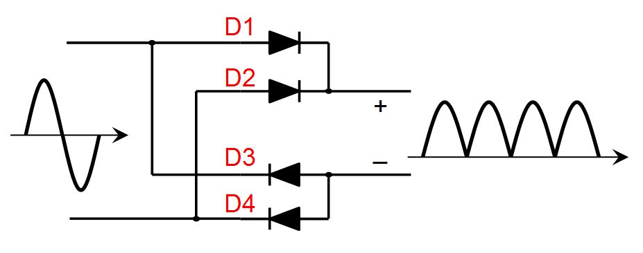
Diode Bridge Rectifier
Now to convert those bumps into DC we just add a large capacitor to the output. Picture below shows the bridge I made with component values.
 Let’s ignore the inductor for now. The capacitor charges all the way to the peak of the wave.
Now imagine it was the positive half of the cycle and and D1 and D4 were on. The capacitor charges to the peak, but as the input starts dropping, in order for the output to go down, the supply must suck the charges away from the capacitor, which means the current flow needs to reverse. But the diodes only conduct in one way and so D1 and D4 both turn off. This results in the output voltage to remain high at the peak.
If there is a load at the output, during the period when all diodes are off and capacitor is holding the voltage, the load will start discharging the capacitor and so the output voltage drops, until the input catches up to the output and starts charging the capacitor again. This is shown in the picture below.
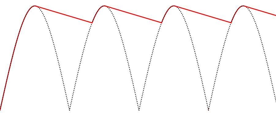
Rectifier Output with Capacitor under Load
The larger the load, the bigger the ripples. This means the capacitor charges and discharges with large currents. This could hurt the capacitor in long run. And this is why I added a large inductor in series to the output capacitor.
Unlike a capacitor which tries to keep voltage steady but can supply crazy currents, an inductor tries to keep the current steady but can have crazy voltages. So as the capacitor charges to the peak, the load current runs through the inductor and charges it. when the input falls below output, now the inductor discharges its current into the load helping the capacitor to provide current to the load. The diodes won’t turn off now as the inductor pushes and pulls current through them.
So now the capacitor gets to hold the output voltage much more steady with the help of the inductor supplying current when needed. There will be much smaller ripple current through the capacitor and it can survive for much longer time. Now instead of output being ripply, the DC level will drop to a lower level as the load increases.
The inductor also prevents the capacitor to charge with very large currents.
Of course, a single diode can also do a similar thing, but there is a great benefit to bridge rectifier, and that is two peaks charging a capacitor compared to one for single diode. It means much smaller ripple on the same capacitor as it discharges less before the next peak hits. Or the capacitance can get smaller which will save in size of components.
All wall adapters I know have a bridge rectifier. The old school ones had a step down transformer, and the a bridge rectifier to make a DC and sometime a regulator for a solid output voltage.
But new switching supplies which are much more efficient, do the rectification right at the high voltage and then step the DC down which switching DC/DC conversion at very high efficiency. Here are some of their benefits:
- As the rectification is done at high voltage, diode drop is an insignificant voltage relative to high voltage and generates very little inefficiency.
- The current drawn from high voltage is a small fraction of output current due to power conversion and so the bridge and input components can be low power and small.
- The switching circuit switches the voltage at much higher frequencies of 100kHz and above and so the step down transformer size is significantly smaller.
Safety Tips
- Dealing with high voltage is always dangerous, less dangerous when it is DC of course. AC is much more dangerous as more current runs through body due to body’s capacitive property.
- Circuit fusing is very important. Proper rating can save the circuit and prevent fire.
- Like I showed in the video, the scope probe ground is shorted to power cord’s earth. So if you are not careful where you connect your ground, it will short that node to earth. In my case I blew my fuse. So in many cases you need isolation between your scope input lines and where you probe. It can be done by simply applying an insulating tape around the earth pin on power cord. The live and neutral wires are already isolated as they pass through a transformer inside the scope. Sometimes I just break that pin off!
- Having a resistor on a high voltage can generate huge power dissipation. Power = V^2 / R = R x I^2.
- When your bridge rectifier is not connected to a load, the output capacitors can hold the 170VDC for a very long period of time and shock you if you touch them. I showed you how I can’t feel them when I touch 170VDC with my fingers, but it shocked me when they touched the skin on the palm of my hand. It is because skin in different areas have different resistance and you feel the same voltage differently. So be careful around high voltages.
What types of diodes did you use ?
Hi,
Right now, I am working on my capstone, and one of the task I need to build a full bridge rectifier. I have two questions
What kind of breadboard did you use? as I know most of them can handle low voltage only, and I need breadboard which can handle high voltage about 200 volts.
What kind of inductor did you use? or is it choke inductor ?
Any advice or recommendation would be helpful.
Thank you,
He uses what is called a perfboard or protoboard (and a host of other names). They come as a pcb with standard hole spacings and either no traces between the holes (what he used) or traces that can aid in layout, distributing power, making connections, or transferring a circuit from a breadboard.
The inductor is not a choke; its purpose is not to filter high frequencies but to prevent high currents. For ratings, go with at least the planned current rating of the rectifier (10 amps in his case) and enough inductance to avoid exceeding the maximum surge rating on the capacitors by a healthy margin.
G’Day Mehdi
In a simple automotive alternator we have six diodes for rectification of the AC to DC 3 positive and 3 negative. Usually 3 more as exciter diodes. my question is could this be built in to modernise alternator output. I am trying to get my head around how I could modify the alternator to make it a full bridge rectified circuit. I am an automotive trainer and trying to encourage students to think outside the box when it comes to automotive electrical training.
Thanks
Garry
I’m interested in making a 3 phase FULL BRIDGE RECTIFIER to charge an electric car.
Were I live in The Netherlands we have 3 phase around 400v. maximum 3x16A.
I wonder which diodes I could use best and were to get them.
https://www.google.com/search?client=firefox-b-1-d&tbm=isch&q=alternator+bridge+rectifier&chips=q:alternator+bridge+rectifier,g_1:3+phase:hfDhY4vQcks%3D&usg=AI4_-kTJjxzojIXTD7HDOBbpuGxTFh1m-A&sa=X&ved=0ahUKEwig_5-z5rzjAhXPVc0KHe56A3IQ4lYILygE&biw=1920&bih=944&dpr=1#imgrc=0yL9rnIEtx3qlM:
Why is the output 170vdc?
Because 120V is the rms voltage. The peak voltage is around 170V.
Pingback: 会唱歌的闪电——特斯拉线圈 - 完整
Hi Mehdi,
love your work! Been spending the last week watching all your videos! Your learning by showing approach to safety is great. But I have a question:
In your circuit for the Full Bridge Rectifier, you use a non-polarized capacitor. But since I am cheap and don’t want to buy new components, I was wondering if it was possible to use a polarized cap instead with a fitting diode in a series connection with the cap, but in parallel with the output of the bridge? So as to keep the cap from blowing up, but letting it feed back into the circuit on the positive side of the output.
Cheers
Maxim
Hi you even dont need extra diod if u pay attention to circuit the voltage that come out of D1 and D2 is always + and the voltage that come from D3 and D4 is always – so u just should connect the + polarity to D1 and D2 and choose right amount of F for ur cap and becarefull that ur cap can support that much voltage .
Do you know how to figure out how much capacitance is needed? I’m trying to build a higher-voltage version of this and don’t know how much it needs
Capacitance depends on load, input frequency, and acceptable ripple current.
Mehdi, I cant find a 2.2mf capacitor in Australia. What can I substitute?
You can put two 1000uF(1mF=1000uF) in parralel to get 2mF, also remember that those caps should have a high enough voltage rating, in your case at least 250V. If you have higher capacity, even better.
I’m your Chinese fan,I’m very crazy about electronic.I watch your video on bilibili,you are so interesting.You are my male god.
why are your capacitors are so big? Could you share part numbers of components that you used in the video?
no need, just choose capacitors that where c = the capacitors 2200 uF /4=the capacity of one capacitor (which you need four of). you can also just get a 2.2 mf capacitor at 170+ volts.
Do rectifiers work with sawtooth wave AC? If so, what is the output voltage compared to the input AC voltage?
It will definitely work with sawtooth AC. The output voltage should still be around the peak of the input, which is input voltage times the square root of 2
Does full bridge rectifiers work with sawtooth wave AC? If so, what will be the output compared to the input AC voltage?
Hello, my name is antipicks and I am trying to make a generator that uses water to turn the turbine. I’ve got an idea on how to make it but I don’t know the terminologies for the materials that I need. What are the elements in an electric generator Called? I’ve google searched it and found a million different answers., seeing how i’m wanting to power my house I need to be absolutly sure I have made the correct choices {I don’t have much money} I tried to make a Tesla Coil but I can’t get the damn thing to work! Thanks for being smart!
Sinserly Yours,
Antipicks
Several issues here, 1st and mostly, why did you make a tesla coil? Its not a generator, its just a transformer. its not special. As said by the god who wrote this article, “THERE IS NO FREE ENERGY, TESLA DIDNT DISCOVER ANY RANDOM MAGICAL ENERGY JUST FLOATING AROUND” – “Everything you need to know about a Tesla coil”. secondly its considerably easier to invest in solar panels and inverters instead of setting up a water wheel. They are more efficient and work more reliably (unless there is no sun which is what batteries are for). 3rd, if you don’t even know how a generator works don’t do this, at the power levels you need you could very well become a burnt hot dog. In other words you will die a horrible painful death. An electric generator works by spinning a magnet inside a coil or vise versa. A dc motor is essentially a generator, wind turbines ARE dc motors. 4th if you are finding a gazillion different answers for this then you are not googling the right stuff. 5th you can ask around and likely easily find the answer from anyone who has gone to middle school before. PLEASE if you don’t know about this, don’t do it. I don’t want to hear about you frying on the news.
i second this response. You are not qualified to work with the power levels and you WILL kill yourself or at a minimum, burn your house down. I have a bachelors degree in EE, and have done more EEing at home than work over the last 10 years, but i’m here getting a few tidbits of info from these types of videos. I already know ALL of the concepts. That’s a 5 undergrad college degree. Just do solar AND wind and enjoy being alive.
but to answer your question, you want an mppt charger. mppt stands for maximum power point tracking. you can run solar, wind, water turbine, bicycle with motor or whatever you want, to charge your batteries.
i wont answer your question any further than that, because i don’t want to contribute to your death.
Mehdi Sir,
I your bigger fan.
Sir please make a video on self oscillating push pull converter for 12v battery to 20v AC or multiple isolated output.
Sir why i am requesting this because now day in micro-gird solar project need multiple isolated power supply to run microcontroller and mosfet driver and we have only source is battery . if we made common ground between them . circuit become more noise .
i found self oscillating push pull converter is good solution to provide the isolated power supply in electronic circuit.
Hi. Great stuff. Can you show on circuit diagram how the short was created ,When the oscilloscope was earthed and blew the fuse.
Hello. How can I step down 17VDC to 12VDC without the use of resistors, in a 20-amp setup? And what capacitors/inductors would be recommended? Thanks.
You would need a buck regulator. use TI’s Webench program to figure your circuit:
http://www.ti.com/lsds/ti/analog/webench/power.page
Hi Mehdi, have you ever try to make a full wave controlled rectifier using SCR? i already try to make it, but all i got is the half wave. Thanks before.
I have 230 V at my home
What type of diodes you used
What are the big 4 black things, they look like capacitor’s?
Is there any power IC (3 pin )
You would have to pick diodes with voltages suited for your region. As well, he did not directly use diodes, instead he used a full bridge rectifier IC (remembering IC just means integrated circuit). The black box just has 4 diodes in it, and the easiest way to mimic this circuit for your region would be to salvage or purchase one of these yourself (rather than deal with diode voltage drops and blah). And yes those 4 big black thingers are electrolytic capacitors, however pay little attention to their values as in your region you have a lower mains AC cycle frequency and higher voltage. Therefore you need capacitors with higher voltage ratings and likely higher capacitance. I will warn though, as you do not seem entirely experienced to be quite cautious when playing with mains voltages. Consider purchasing a step down transformer to attempt your first full bridge rectifier first (ensuring it is not an isolation transformer so your RCD or whatever its called can still save your life).
To clarify what I meant about isolation transformers – don’t get a variac. Get a step down transformer to lower the voltage, and ensure you understand enough to buy one with correct inductance values to not supply high current, but still none of this matters if you aren’t careful connecting this new transformer to your mains voltage anyway. So now I’m not sure why I bothered with the comment.
Can you tell me all the components like
Diodes
If there’s an IC
What are the big 4 black things
The black parts are capacitors
He doesn’t use any regular diodes, he actually uses a bridge rectifier IC instead. It’s the black box at the end of the circuit board, and it basically has the 4 diodes built in.
I would like to know, if it is possible to make a bridge out of thyristors. There is couple of websites I checked, however I get a half wave instead of a full wave every single time I connected the Thyristor bridge to the Oscilloscope. I’m using Multisim 14.00
Dear Mehdi…
can u please answer these questions?
1) what kind of non high voltage capacitors did you use for this?
2) did you use any op. amplifiers? if so, mention the type.
3) what kind of resistors did u use?
thanks please reply!!!
what should be the value of C and L
if i use the power supply of 220v AC
If its not too late, I think I could help.
The voltage you would get is about 220*√2 = 311 VDC. So the capacitor at the end is to smooth out the rippeling from the bridge rectifier, so the voltage on the capacitor should be 400V. The capicity doesnt really matter, whether you have 110V or 220V. So the capacitance that Mehdi uses(2.2mF), is the one you should use.
The inductor is to filter the DC, so something around 30mH is enough. Make sure is can handle the current and voltage you want to use.
\
i also have a 50 amp transformer what value of a rectified diode i will used & value of a capacitor tn sir…..
sir mehdi i have a 12amp transformer 13 o 13v DC what value of a rectifier diode i will used & what value of a capacitor i will used?
Hi Mehdi
I am new in electronic.according to this web site the out put DC voltage must be 0.9xVac
http://www.sowter.co.uk/rectifier-transformer-calculation.php
on section 4 you can see your circuit and their circuit are same but your out put voltage is different.
could you tell why out put voltage are not same?
I’m not sure exactly how they have calculated the outputs, but from their description they are taking into account the effect of the voltage drop on diodes. In my case above I assume that amount is negligible as my AC voltage is much higher. The diode drop total would be around 1.5V under load and my output voltage is ~170VDC, so we can ignore that drop as it is less then 1% of total. But that website has a transformer that maybe reducing AC level and so the diode drop would be significant and needs to be taken into account.
from were did you get your 30mH inductor
I would it myself, took a toroid core and would some magnet wire around it.
how to know that exactly it is 30mh ?
Depends on the number if turns the inductor has and I also believe the thickness of the wire is involved and the radius of the toroid core.
Or using LCR meter
What type of core are you using? I made a similar one in size and wiring gauge but it’s only 0.2mH. (yellow/white core)
How are you able to withstand so much electrical shocks in all your videos without being seriously injured? Is it photoshopped or are you actually getting zapped for our pleasure?
Hello Mehdi, your full bridge rectifier video is very funny! If you have the time i would like to ask you if your circuit is compatible to power 50 power leds (3W each) in series (50 x 3,4v =170v) with a current of 700mA on 110v ac?
I would like make long tracks of neutral white leds for my art studios, i have good knowledge of electronics but not too much with high power and i don’t want to have capacitors explode in my face if i do errors…
thanks for your time
Andre
I love your videos, and was hoping to make one of these to drive a tesla coil for a scchool project, and had a few questions,
What was the total output voltage and current of your system?
What was the diode that you used?
How many turns are on the inducer?
And what is the ratings on your capacitors/ how are they hooked up? In your schematic it looks like you only have one, but in your video there is 4?
Many thanks,
ok, scrap that first question…guess I just didnt read carefully enough. I am still interested in the others tho Thanks!
Hey electricboom guy, I love your videos, they are awesome, I am really interested in what you do, I started learning about electrical engineering this year, and I know this program is REALLY fun, but the teachers and the textbook don’t do a great job at teaching about these awesome things (ex. capacitors, inductors, logics[word problems, jk flip flop, sr, counters, encoders, decoders, etc.], diode, rectifiers, bjt, jfets and etc). I was wondering how did you learn everything and how can I understand it to a point where I can do cool stuff with it.
How can I get 170VDC from a 12VDC input? Would this device be appropriate to achieve my desired voltage
You would have to turn the 12VDC into 12VAC and then use a step up transformer that would step 12VAC to 120VAC. On the side of the transformer where the 120VAC is outputed will be the input of the circuit above. Hope this helps!!!
hii how can i design a filter circuit for full wave bridge rectifier at 230v,50hz supply. what will be the value of capacitor and inductor in the circuit.and i also use 12-0-12v transformer in the circuit.plz send me detailed calculatiõn for fïndïng the value
by 2.2 mf, do you mean micro farad ?? And how many turns do i have to put on my inductor to be used with 240 volts ?? Waiting for a answer bro !!
No it is milli-Farad. Not too many turns. The amount of Farad you get from your inductor also depends on the type of cores you use. I have a core at work that with only 4 turns you get around 6mF. It is a special core though.
Hmm I think you mean Henry’s. Inductors are measured in Henry’s not Farads
I live in UK and have 230v ac coming out of wall, how can I use this circuit with this voltage? I want my 10kv transformer to output DC for my tesla coil and a 10kv rectifier scares me!! What do you suggest??
By the way your videos are hideously funny yet informative, my mistakes are similar, thankyou
Tesla coils don’t use 10kV DC input. I don’t think you can easily find a transistor that can switch a 10kV DC. You need a different circuit, the traditional kind. Good luck!
I’m in the United Kingdom (240VAC). How would I alter this design for your Tesla Coil circuit??
The Tesla coil ended up not using this because its circuit couldn’t handle such power and would blow up. I just use a DC 30V. I would need to change my Tesla coil circuit to be able to use the rectifier.
Hello Mehdi. Thank you for your videos.
I am trying to duplicate your design here that you have shown with the diodes but my fuse keeps breaking and I am trying to troubleshoot the reason.
I have tried with a 10V AC and my circuit works but when i plug it into the AC wall adapter the fuse breaks.
I am using a 3.3 milliF capacitor that is rated above 200 volts. The diodes that I am using are the 1N4004 diodes in the same configuration that you have.
Can you tell me what my problem is? Do I need a load for the circuit to work?
Thank you.
Regards,
Vik
Also, where did you get your inductors from? I can’t find exactly what you have.
Regards,
Vik
I bought the toroid core and wound my inductor. You don’t need exact same inductor, you can design based on what you need.
I am trying to make the tesla coil that you made. Is there an inductor that i could order online that does the same job?
not Realty. You could wind your own or by a kit or maybe just the coil from OneTesla.com
You haven’t had connected you output DC to any earth or neutral, have you? That would short the actual AC. Also I hope your AC is not 240V and is 120V! Otherwise it should work fine.
I am in the US so it is 120 AC. But how much current should that inductor handle? What is the maximum current that it is going to flow through that inductor if I am trying to make something very similar to the tesla coil that you made?Can you also give me the part number of the rectifier that you are using?
Thank you much fro responding quickly and for your time.
Regards,
Vik
And the part number of the inductor as well if you don’t mind.
Regards,
Vik
Pingback: Make a Human Powered Charger for Mobile Phones | ElectroBoom
I just get artictle about tunnel diode, if you need to get more information about this electronic device check this.
Cheers. Loads of data.
It’s an amazing article in support of all the online viewers;
they will obtain benefit from it I am sure.
what is the difference between “Slayer exciter” and “Zero Voltage Switch” ?
Completely different things
short and simple answer lol
For some reason my ZVS driver doesn’t work on this power supply at least when I connect the flyback transformer no voltage can be measure at the output of the circuit, before connecting the transformer, an output of 26 volts can be seen
Hey, your videos are awesome, I tried making this circuit using a diode bridge and inductor and capacitors from a computer PSU I took apart. The capacitance is 2.4 mf and I am not sure about the inductor. My mains supplies 240 volts AC and I read on the previous comments to increase the power rating of my components. I have 13 amp and 15 amp fuses and more capacitors but the capacitors blow up when i connect the circuit to the mains. Would you recommend I use the 13 amp fuse or 15 amp fuse and a step down transformer to bring down the voltage from 240 volts AC to around 120 volts AC. I require a 12-36 volt 10 amp continuous output as I am driving this circuit, a ZVS driver, http://www.instructables.com/id/ZVS-Driver/ . I really enjoy your videos and you are an inspiration, looking forward to your response and also the new Tesla Coil schematic you are going to release (I hope :D).
Regards,
A FAN XD
Forgot to say that the capacitor’s are rated at 200v
Ok, sold the problem, I now have 300 volts approximately in DC, I need to bring it down to 12-36 without a transformer, any way to do this?
Look into Buck DC/DC switching converters.
Thank you for your help in advance, keep the eyebrow waving 😀
Hey I just got a transformer to step down the voltage so it works, thanks for your help, however when I connect it to the highvoltage driver the voltage in the high voltage driver reads as 0 when the transformer is connected and 26 when it isn’t, is there anything I did wrong?
I got problems when I did the experiment. I used 60mH inductor, 3mF\450V capacitor, 220V\50Hz AC. My 10A fuse broke when I plug in. I don’t kown why. Should I use bigger inductor to reduce the instant current?
Or should I use smaller capacitance to reduce charging time?
Your fuse value is too small I believe, try 13 then 15 but be careful and do more research since I am pretty bad at this myself, good luck 😀
Hi Mehdi. Can you give me a helop about the diodes?
There’s any problem use a zener diode or i need to use a normal one?
And what values you recommend ( Whats, max current …..Etc) for the diode
You can get the diode he showed in the video from a good quality PSU but zener diodes you have to look at the data sheet to know about the power specifications.
NEVER use Z-Diodes for rectification.
They become conductive in reverse direction from a certain voltage level on. The result would be a short circuit.
Z-Diodes can ONLY be used for stabilization purposes at low power applications.
Hey there, You’ve done an incredible job. I will certainly digg it and personally recommend to my friends.
I’m confident they will be benefited from this web site.
Hey man ! nice project can you tell me the exact value for each component ? D1-D2-D3-D4? Pleaseeeeeee….
that depends on your power output, otherwise just look for diode bridge on digikey.com and you will find millions of options.
Hi Mehdi,
I need to power a device that pulls 1.5 amps at 6 volts. I don’t have a power adapter that can supply that, but I do have two power adapters that supply 3 volts at 1.5 amps. Is it possible for me to put them in series to produce the 6 volts needed?
yes, that’s what you would do
Hi mehdi, i have a treadmill motor, and a treadmill curcuit board which wont work. It has all of the components including a large capacitor and a rectifier. My knowledge in components is very limited.
\What do i need to work that motor, it requires 90vdc and around 1kw
Well, with your limited knowledge I would be afraid if you touch the high voltage. But if it has the rectifier, you need to plug it in to 120VAC and connect the rectifier output somehow to the motor to run it. That sounds pretty dangerous not knowing what you have! Hope you have a will…
Hello Mehde,
sorry to bother you again but I had some problems on my way to HV:
I build the full bridge rectifire acording to my plan I posted here. Circuit is the same as yours but my values are:
L1 = 109mH;
C=220uF+150uF+100uF (all parallel, all 400V rated)=470uF
When I pluged it in my fuse (2A) blew up. I tried with 6A Fuse and this time my home fuse blew up! I thought the capacitors are the reason because ~230V (as I mentioned I live in Europe) with a quite high capacitance might be like a short-circuit. So I tried with only on capacitor and used 220uF and it worked 🙂
Do you also think it is the capacitance? It can’t be an internal short cause i tried it with low power (low voltage) (9V, 12V 5A, 24V DC) and the circuit worked fine.
And I was thinking about using a dimmer switch infront or behind the build in fuse to control the outcoming Power. What do you think? Would it work and if so what would be better/ more safe infront or behind the build in fuse?
Thanks for help
and please go on with making your great videos!
^^
Matze
Hi Matze. The capacitors usually charge pretty fast and won’t blow a fuse. Your capacitors are smaller than mine and should be even less harmful. Maybe your large inductor and capacitors oscillate with city power frequency and do something funny?
You could use a dimmer before the bridge on AC line. But it will work when you tune it below 50% when the peak starts to get smaller.
Hello, Great video.. learning while laughing is the best!
I hope you can lend some guidance on a new project of mine.
I am trying to convert AC 6v/3w output from a bicycle dynamo hub into clean usable DC 5v/USB output for handlebar mounted smartphone, etc.
On a basic level, Im pretty sure I will need a bridge rectifier like in your example, however I am no EE, and I do not know how to compute the component values for the voltages I’ll be working with. 🙁
Also, one complication is that as bicycle speed changes, power output from the dynamo will fluctuate (charts available) or even cease if the bicycle stops.
If hub output falls below what is needed for conversion to clean usb output, the circuit should cut off at a safe level as if unplugging the microusb cable.
Is there an easy (DIY) way to maintain clean USB output given the variable input of a 6v/3w bicycle dynamo hub?
More info:
i have a PB500Cs from Adafruit (https://www.adafruit.com/product/1944) to act as an In-line battery cache for usb devices on the bike, whch already works great. Now, I want to feed the PB500C’s DC5v USB input with power from my dynamo hub.
Any advice or help would be awesome!
Thanks!
Thanks!
Hi, seems like the bridge rectifier and the PB500 is really all you need! Just rectify the voltage from dynamo through the bridge rectifier and feed it to PB500. It will charge a battery and provide USB voltage output. When the dynamo has enough power it will charge the battery. In either case the board provides stable output voltage, unless the battery looses all its charge.
Good luck!
Awesome, simple is good. Thanks for the info. H
oping to move forward with this project soon, but sadly, I am still a little clueless on choosing the right components.
Can you lend a little more guidance on what values I will need for the diodes, inductor and caps for my +/-6v/3w AC to 5v/500ma project???
Also, someone told me I should use Schottky diodes for this type of rectifier. Do you concur?
Wish I had a little more exp with circuits — gotta start somewhere! 🙂
Thanks again!
You don’t need anything too special. Inductor is not necessary really for your application. Just find a bridge rectifier that can do over 1A. Anything wold do as your voltage and currents are pretty small. The diode bridge with 4 diodes comes in a single package. You don’t need Schottky as your AC frequency is pretty small. Put a large capacitor, over 1mF, 10V should be good.
what if i connect an usb wall charger to the dynamo and the phone in the chager? would it work? since the wall charger will convert AC to DC and output 5v, the thing is most of wall chargers says the input is 100-240v
Pingback: Music, Magic and Mayhem with Tesla Coil | ElectroBoom
what is L1?
It is an inductor
ohhhhhh ok thanks
is the inductor necessary? I mean do I really need to use it , because I can’t get it .
It is good to have some inductance there to reduce the ripple current on capacitors. If you are not drawing too much current from the rectifier, then no inductor is OK too.
I’m drawing about 220V DC
You should say how much current you draw.
oh sorry it is the city power im not sure how much amps is that but i live in europe
Which capacitors should I use ? Can you tell me how many volts and microfarads it needs to be ?
The values I used are on the diagram above. I used four capacitors in parallel to get that.
Thanks
Hello Mehdi,
I don’t live in the US or Canada. Would it be possible to make this project with the same component values in Europe (230V DC 50Hz)?
I want to use a 2.2mF /400V, a 150uF /400V and maybe a 100uF /400V capacitor in parallel
and I could use a 25mH, a 37mH or a 109mH choke. What do You think will work best?
Thanks for your videos!
Mat
All those values will work. The larger you make your capacitance and inductance, the greater filtering you will get. The ripples on the supply would depend on the load you are driving with it, and how clean you want to make it.
Hey Medhi,
thanks for helping!!! The load will be a tesla coil; actually the slayer exciter. I try to do your experiments but I am planing to do some more testing as I did with the spark gap tesla coil. I did lots of experiments with this one and also contacted Steve from Rimstarorg who helped me as well.
Slayer doesn’t take much power. >100uF capacitors would work fine. Good luck!
Hi Mehdi, you mention that modern switching supplies are more efficient because they do the rectification at the high voltage and then step the DC down. But I thought step down transformers only worked with AC current? How do you switch to a lower voltage with DC? Thanks.
You make a high voltage DC, then you switch the DC at higher frequency, like 100kHz to 2MHz over an inductor or a transformer to convert to a lower level, and convert it back to DC. Those inductors or transformers will be much smaller as they will be working at high frequency, and also more efficient.
Mehdi what store should I go to to find the supplies
Where do you live? I do Digikey.com or .ca
Thx
I loved as much as you’ll receive carried out right here.
The sketch is attractive,your authored mateial stylish.
nonetheless, you command get got an nervousness over that
you wish be delivering the following. unwell unquestionably come further
formerly again since exactly the same nearly a lot often inside case you
shield this increase.
Hey,
Could you tell me what the ‘Earth” on the PowerCord.
Thank you,
Nick
Earth usually is connected to exposed metals of an enclosure on a product. If there are no exposed metals, then we don’t need to connect earth.
hey mehdi
can you expalin me how you decide the rate or scale of your component
for example why 30 mf capacitor?
i wanna know how can i know which capacitor i need?
thank you
Don’t write my words down, but using a software to simulate the circuitry is a nice way of dimensioning stuff.
hi
i want to know how to calculate theoritically ….
hi mehdi
regarding to the چهارشنبه سوری i am looking for an easy circuit 4-channel remote control to control my things (firecracker – rockets – TNTs – dinamits and so) 🙂
here is so many pre-created modules but i’m not an electronic engineer and i don’t know how to write program for them ! also they are expensive for a simple remote !
i know this project maybe without electro-shock or danger and this is abusive for u but plzzzzz 🙂
I’m going on a plane now, so no time to research! Good luck!
Sir, I have a signal conditioning circuit built of amplifiers and opamps. I wanted to know the best way of measuring the power consumption.
Does the current remain same throughout the different stages of the circuit..?
My circuit is being operated at 3 V.
Please tell me how I can measure the total current drawn by my circuit
There are multimeters that do current measurement. You put them in series with you supply and measure current and that multiplied by supply voltage is your power. If you don’t have a meter, put a small series resistor to power and measure the voltage across it. Voltage divided by resistance is current.
Hi mehdi, where do you usually source your electrical components from? (Capacitors, resistors, etc.) I’m from Ottawa and I’m having a problem finding websites for suppliers near me.
Thanks in Advance!
The best one I always use is digikey.com, with next day delivery. Other good ones are: mouser.com, newark.com
Could you make a video showing us how to make a DC Amplifier circuit or perhaps a DC to AC converter? I would appreciate it.
I can try, but will take a long while, because I’ll first do what I like more!
I always learn something and laugh watching you!
I have a supply that can deliver 12VDC 100Hz, when I add a capacitor to filter it, the voltage jumps to 18 volts! why is that? I noticed that too when charging a capacitor with a pulsed DC source. For example, I tried to charge a 4.7mF 16V capacitor with a pulsed 15VDC source. When I checked the voltage of the cap, it was around 21 volts.
Sorry for asking too much questions xD.
What’s a 100Hz 12VDC? It’s either DC or 100Hz. I assume it is 12VAC and the peak of that is 12 * 1.41 ~ 17V. That could make sense. I don’t know what kind of supply you have there.
The supply is brutally simple: just a transformer and 4 diodes to rectify it. It outputs 12VDC at 100Hz.
If I put a capacitor at the output, it jumps to 18VDC 0Hz ( no load connected)
Ah OK that makes sense now, so you have those consecutive humps at your output. Of course your multimeter doesn’t measure peak, but measures the RMS which is lower than peak. But when you add your capacitor, it holds the voltage at peak, which is higher. I think that’s what you are seeing.
Ohhh, so you are saying the supply doesn’t output a clean 12v pulsed DC, right? that makes sense. The capacitor will hold the voltage at the peak of the signal, witch is 18 volts.
If I get an oscilloscope, I’ll check the waveform with it. Thanks Mehdi!
You’re welcome, but even a clean pulsed DC doesn’t show as 12V on the meter, because it shows the RMS voltage which is less than 12V for a square wave 12V.
Hmm, power resistors have an “Ohm-Joule” rating thing. For example I have a 10W 3 “Ohm joules” power resistor.
What is meant by ohm joule?!
That’s the first time I I hear Ohm-Joule. It is usually 3 ohm 10W or something. Maybe it is some special component with special rating I’m never used.
Nor me. Ohm-Joules never heard of. In the game for 40 years.
Here’s a picture of the thing, it’s a 5W resistor:
http://i59.tinypic.com/2jwaj4.jpg
Not sure, but it might be a 3 ohm jumper rather than joules. Do you have a link that explains such resistors?
Sadly, no. The “J” may not even stand for Joule at all. It might be something else.
Google “5W resistor” there are some that contain an “Ohm-J” thing.
Well, if you want, ask your subscribers about this thing. Maybe some one knows about it. Thanks Mehdi.
Hi it means that it is 5W 3 Ohm resistor and J stands for tolerance of ±5%. (C – ±0,25%, J – ±5%, M ±20%, etc.) That means that resistance may not be 3 Ohm exactly, but it can be any resistance from 2,85 Ohm to 3,15 Ohm.
Source?
This link can serve as a source for the J standing for tolerance, (if you click on the image) Also you can browse some components.
http://www.digikey.com/es/resources/conversion-calculators/conversion-calculator-resistor-color-code-4-band
That makes sense. Thanks!!
How did the fuse blow up? I don’t get it.
When the sine wave goes negative, D3 turns on connecting the live wire to negative output. If you connect scope probe ground which is the power plug earth to negative, it will be shorted to live wire through D3.
Many thanks, Sir
I understand it now
https://ibb.co/KFF82kZ
Sir can this circuit be used on 220v???
Sure. 220VAC(rms) has a peak of around 311v( 220 x sqrt(2))
Just make sure your capacitors are rated properly to handle this voltage.
As well as the diode bridge rating…
hey brother in our country we use 220 VAC . would you please give the exact components list for 220 VAC in this circuit. waiting for your reply
Gotta love the risks, awesome video once again Mehdi!
Hey man! I was wondering if this would work with the european standards of current? As in 230VAC and 50Hz. Otherwise could you tell me which capacitor and inductor to use please?
With friendly regards,
Lucas
The 230VAC is an RMS voltage, or root mean square, also called effective voltage. If you use 230VAC to power this circuit, you’ll get around 325VDC (230 x sqrt(2))
So your components must be rated properly to able to handle this voltage.
Yup, and keep the rating a bit higher to have some margin.
For this, can I use two capacitors of 250 mF 250V in series? Or it will still blow up?