Have you had a power outage and wished you didn’t have a power outage?! You might have the tools to help the situation:
Well I guess the UPS (Uninterruptable Power Supply) devices are not super expensive nowadays, and if you live somewhere that power outage is common, I really recommend you get one. They are always plugged in, so always keep their battery charged and when the power fails they automatically power on and keep things on.
But hey! you may get surprised by an outage outside home like happened to me. At the end of the party I realized I had an inverter in my car. I asked the host for a drill battery and he had an 18V one. Unfortunately it was too high and my inverter started complaining. I thought maybe I connected it backwards, and being so sure that an inverter design must have adequate reverse polarity protection, I connected it backwards and it blew up!!!! DAAAAMMNNN!
I mean what the hell man! In any product where they leave it to the user to connect the power lines, they MUST make sure that their device can withstand a reverse polarity connection! Isn’t that obvious?! I mean probably they get half of their products returned because some dude like me connects it backwards. And the solution is so simple too.
Below is the circuit they had in their design. The fuse is made of 2x 25A fuses in parallel. The diode is a general purpose power diode. I have seen this in some designs before and is a dirty way of doing reverse polarity protection.
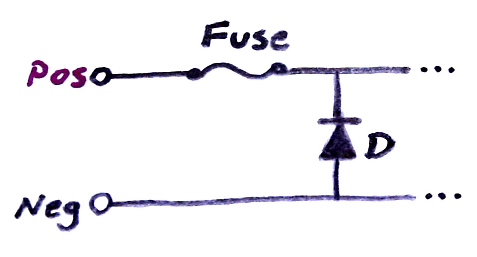
Reverse Polarity Protection Using a Fuse
The thought behind it is that if somebody connects the supply backwards, the diode will be forward biased and clamps the voltage across the circuit to a small negative value, like -0.7V to -1V, and that should be enough to save the circuit. In return this shorts the supply and so there will be a large current that blows the fuse. So the circuit is saved and you just need to replace the fuse.
Sometimes the designers use the resettable fuses instead (thermal or PTC) or breakers, so that the user won’t have to replace the fuse. Still, this method is generally good for low power circuits.
For a high power circuit like an inverter where there could be large nominal operating currents, the fuse has to be rated much higher like 50A in my case. So to blow the fuse in time, the current has to be well over 50A. This, through a regular diode, will generate a large negative voltage above -2V. Such higher negative voltage can damage the circuit. So although they have a protection, it is not protecting anything, and they mention that in their datasheet too!
The text below is taken from a Stanley inverter datasheet:
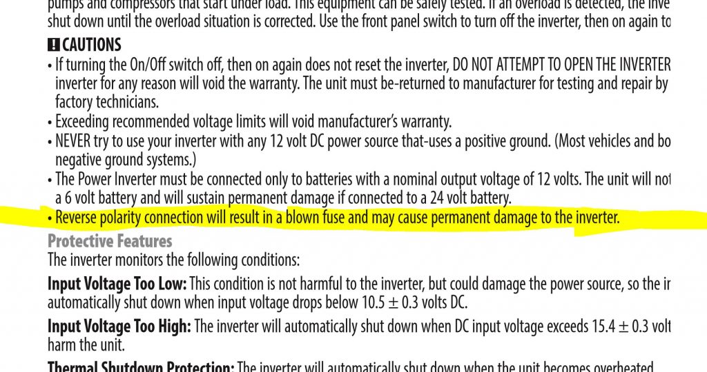
Inverter Datasheet on Reverse Polarity
In my experience, a type of rectification works much better than this circuit. You might suggest a regular diode, which is fine for low power circuits. But for a high current circuit the diode would waste a lot of power (Vdiode x Current) and would need power diode and large heat-sinking just for normal operation. I rather use the following circuit which utilizes a MOSFET for reverse polarity protection.
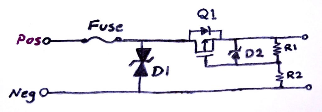
Proper Reverse Polarity Protection
We still keep the fuse, in case there is a short on a failing circuit or an output short. The fuse would only open in cases of catastrophic failure.
D1 diode is a TVS (Transient Voltage Suppressor) diode, which is like a zener diode that starts conducting at a defined reverse voltage. What I suggest here is a bidirectional one, which means for example a 40V TVS won’t conduct until it is above + or – 40V. It is there to absorb low power transients and spikes, like ESD or low power engine power transients. It conducts at high voltage and with the help of the transient source output resistance, clamps the voltage below a certain level to protect the circuit.
Now the Q1 MOSFET circuit is what does the rectification for us. In this example Q1 is a P-Channel MOSFET. How it work is like this:
- Imagine everything is off and the output voltage is zero at the beginning.
- When input is applied correctly, the supply voltage passes through the body diode of the MOSFET raising the output voltage.
- As the output rises the gate-source voltage of the MOSFET rises through R1-R2 resistors and so Q1 MOSFET turns on.
Having a MOSFET on is much better than just a diode, because it can be chosen to have very small ON resistance and so wastes very little power compared to a diode.
Now in case of a reverse polarity, if the MOSFET was already off, the body diode of MOSFET also blocks the output from the reverse voltage. R1 keeps the gate-source voltage at zero and the MOSFET remains off. And so the output is blocked from the reverse input.
If we start from a positive supply and then the supply goes negative:
- MOSFET starts from ON state
- As the input drops, the output drops too as MOSFET is on, and so does the gate-source voltage of MOSFET through R1-R2 resistor
- The MOSFET turns off as input is passing zero and gate-source voltage is zero
- When input is below zero, MOSFET is off and blocks the circuit from reverse voltage
The gate-source voltage of MOSFETs is usually rated for 20V or below. This is the reason for having D2 zener added to R1-R2 resistors, so that it can clamp the gate-source voltage below 20V. An example of good values is a 16V zener, 47k for R1 and 10k for R2. The MOSFET should also have a drain-source voltage rating above the maximum reverse voltage.
If your input NEVER rises above 20V gate-source rating, then you can ideally eliminate R1, R2 and D2 and directly connect the MOSFET gate to input negative line.
Also, the MOSFET circuit can be flipped to the ground side using an N-Channel MOSFET. The benefit of N-Ch is that the ON resistance of N-Ch MOSFETs can be much lower than P-Ch, and so can handle much higher currents.
Now every MOSFET has some input capacitance that combined with gate resistors, slows the response time of MOSFET. So if the input switches from positive to negative super quickly, the MOSFET can conduct for a while in negative voltage as long as it takes to turn the gate-source voltage off. This could damage the circuit, so:
- Pick R1-R2 that combined with input capacitance of MOSFET, results in a time constant much faster that a negative going transient edge.
- Have large capacitors on the output to absorb high-speed low-power negative transients.
- You can have a reverse diode on the output of the MOSFET, so that it conducts for a very short period of time it takes for the MOSFET to fully turn off. Such diode won’t blow a fuse as the time it conducts is very short.
One last note on this circuit, if you have large capacitors on the output of the MOSFET, make sure the MOSFET can take the in-rush current required to charge the capacitors.
Wow! I didn’t even know I was going to talk about this subject until my inverter blew up! But I guess that’s out of my system now. Let’s talk about powering a home using an inverter.
Like shown in the following picture, the output of an inverter (green pulse shaped wave) is not a nice sine-wave like the outlet voltage (yellow). The city voltage is created by actual generators like water or wind turbines and those create sine-wave voltages. But in an inverter, they simulate the AC by switching the battery voltage across the primary of a transformer, and the transformer amplifies the voltage to 120VAC. Maybe I should make one myself.
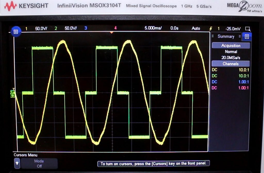 They both have the same RMS value of around 120VAC. But they don’t have the same exact frequency as their frequency sources are different. That results in them being out of phase as they keep moving relative to each other. So when one is high, the other one can be low. Connecting them will short them and result in a large spike. So even if they were both sinusoidal and in the same frequency, if they were not in phase, it would cause a high current short circuit connecting them.
So you might wonder, how can those houses with solar panels feed power back to the power grid? Well now you know that it is a tricky business. Those inverters create voltages that are sine-wave, and have the same frequency and match their phases to grid voltage, and are slightly higher voltage so the power flows from them into the grid.
And this is why powering a room through an outlet using a regular inverter, the breaker feeding to that room must be opened. That way after the outage is resolved, city power doesn’t short to the inverter power.
Anyways, it might just be better if you have everything you want to power connected to a power bar and just plug that into the inverter, or just by a UPS!
OMFG… Dude, I think that you should research the difference between normal car batteries and batteries that are used for backups (There are 2 types of deep cycle batteries, I tell you this so you don’t buy a marine one)
PD:There are “Starting Lighting and Ignition” and “Deep Cycle” lead batteries
Hi, Mehdi.
I like your videos very much. It’s funny & educating.
I am planning to install a solar energy system for my household.
Would you please do a video about it? Especially on how to install it, DIY-style, and how to do it so that it is most efficient, most efficient & most economical, and safest.
Also, please explain the terminologies used in this project.
My consumption is estimated at 18000 Wh at the lowest and 32000 Wh at highest for one night. At day, consumption is not much. Perhaps hovering at 2000-4000 Wh.
Thank you.
Hi,
Can you give me idea how to shutdown output in case n mosfet fail?
I have dc to dc converter which uses n mosfet in series at ground where positive is common. whenever mofet fails due to load or heat it gives output volt = input which in return make smoke of my beloved end load.
hope there would be some help
It was a great article and video. Thanks for this good work and please work carefully. Have a good day!
You are cool 😎
I want that mooshim..
How to have it?
U R Either acting like the biggest moron in the world are are that person who is trying to act like someone who is not.
Funny how U break the place up all the time 🙂
Ok, the suggested protection circuit is all fine and dandy. However, what if the power loss generated in diodes was a non issue, like a power supply with extra current, for example. Wouldn’t it be better, then, to protect the circuit with our hero, the FULL BRIDGE RECTIFIER!!!? That way, there wouldn’t even be a wrong way to connect the input. How convenient is that?
In fact a puny single diode connected in series with the main board will work. Too much full bridges will only bring much more cost and much more opportunities to blow up! Handling a current which could be as high as 50 or 100 amperes with a single diode seems much more plausible than with a FBR(you know, the hero).
Hey YouTube and Facebook is blocked here in China
So what? This has nothing to do with the topic!
So get together, overthrow your backward, despotic, repressive government, and change things … or stop your whining.
U R SOOOOOOO Lucky
Express VPN. His sponsor for quite a few of his videos. Or was it Nord VPN?
Finally,I have logged in to this website.Yeeeeeee
Stop spamming, it’s really childish and stupid. If you want to spam, do it somewhere where it is allowed.
You need to be FULL BRIDGE RECTIFIED……oh no, an ESD zap will be enough to give you a lesson.
I know you’re from PRC and so do I. I’ve met you on Tieba, a BBS system in which spamming is strictly prohibited. I believe you will certainly behave as politely as you’re on Tieba.
Finally,I have logged in to this website.Yeeeeeee
Finally,I have logged in to this website.Yeeeeeee
http://v.youku.com/v_show/id_XMjUyMDU3NDk2MA==.html?spm=a2h0j.8191423.module_basic_relation.5~5!2~5~5!5~5~5~A
http://www.tudou.com/programs/view/62o7dn1E3_I?tpa=dW5pb25faWQ9MTAyMjEzXzEwMDAwMl8wMV8wMQ
Hey Mehdi S can you do a video about a “shock gum prank stick” It is a basic gag that is meant to be a schoking prank for some one to pull and and get shocked painfully. I would also like to know how it works (don’t forget to make a video about an EMP)
I would like you to make a video about Shock-gum gag
It is a prank toy to shock people with
i would also like to know how it works 🙂
Mehdi S. COULD YOU PLEEESE MAKE AN EMP ALSO
EMP sounds BOOM
Hi! Love your “experiments”!
From where can I get this handy “pussy”-Meter?
Greetings from Germany 🙂
Ives
Maybe using a relay instead of MOSFET would be more cheaper? Just need a relay connected in series in the main circuit and using a diode connected in series in the relay coin.
ahahaha the “details” go in one and out the other but i grasp the idea as usual but what i adore is your humor!! you are AWESOME!! thanxs for the info! (still giggling!….)
Pingback: Powering stuff when there is a power outage - We Vloggers
Where the give away sing up ?
Pingback: Powering stuff when there is a power outage - Trendz Pop
Your video was great. But you are showing people how to power stuff threw a wall socket which is very dangerous during a power outage. I am a journeyman lineman and I will tell you right now that kills a lot of us. Due to what’s called back feed. What people don’t realize is that when u do that it goes from the secondary side and out the primary side which now is hot. That is what kills us. We do ground our lines after we check that it is dead and also epz our wire. People should still know never to do that. Plz plz. Let your followers know this so I don’t have to hear that one of my brothers died from back feed. And also if the power company has not gotten there and they do that u could possibly kill a person next to the wire because of that. This is all happened before. So plz plz let them know
I am also a journeyman electrician and I second this. Great videos, but this could be incredibly dangerous if done incorrectly.
http://www.electricianslibrary.com/what-is-backfeeding/
Live your videos friend! I’ve been watching them for several years. How do I get that awesome meter set up?
May i have the Giveaway ?
Where do I sign up for the giveaway?
Love your videos.
Q for u:. Can u plug in one of those UPS to the (forced air gas) heating system? How long would it last? The furnace burns natural gas but it needs electricity to run the fan and start the fire.
I live in an area where we get occasional power outages and they can last up to a week. They are rare enough for me not to invest in a power generator but it sure sucks to be in a freezing house.
Thanks!
+Andrea
There are two fans in use when in heating mode of a forced air furnace, and you have to take in consideration of the all the electronics within it to include: hot surface ignitor, rollout switch, high limit switch, negative pressure switch, induced fan motor, electronic gas valve, flame sensor, 24v transformer, thermostat, blower motor, capacitor, circuit board, and zone board if you have one. Plus many other factors include what type of blower motor you have…IE: Permanent Split Capacitor, ECM, Variable Speed, Booster….etc. Also if there are any restrictions on the air flow it will cause the motor to work harder causing higher amperage. Like a dirty filter, dirty indoor coil that the air has to pass thru, even with just 1/20 inch of dust on the blower blades can cause a loss of energy efficiency. A modern gas furnace pulls between 3 and 10 amps during run and between 15-30 amps during start. It all depends on age and conditions. AFUE and SEER. It would be somewhat safer for you to power a space heater via UPS or AC/DC converter from a car battery in my opinion. To calculate how lone it would last depends on the wattage of the space heater and power source. Without all specifications of the equipment (battery, voltage, watts, amps, etc), it would be impossible to give a exact time of usage, just an educated guess.