Is there a microphone embedded in our lighters??
Well, it is safe to say there is no microphone in your regular lighters, keyword being “regular”! BUT the piezo element there is very much the same thing used in piezo microphones.
So like I said in the video, a piezo crystal can be used as an electrical load or a generator, based on an effect called piezoelectricity. There are tons of applications for both cases.
As a load they can be used to:
- tune frequency in electronic oscillators. They are made into components such as crystals and crystal oscillators. There are different types of those, and depending on the size of crystal they can tune for different frequencies.
- generate audio. They can be made into speakers and buzzers. In watches and alarm clocks those piezo speakers are what make noise.
- generate ultra sound. Same as audio speakers, ultrasound speakers use piezo crystals to generate ultrasound tones with precise frequencies, which are also used in mist generators!
As a generator, they generate electricity from vibration and can be:
- any type of vibration sensor.
- a microphone, picking up air vibrations, such as another ultrasound speaker’s output or just audible sounds.
- Surface vibration sensors, they can pick up waves traveling on the surface of solids.
- Low power generators. They don’t really generate much power, but can be useful for electronics that need small power, like a lighter.
So I was trying to make a microphone from the piezo crystal in a lighter. Now I’m not sure if the crystal is the right material they use in commercial microphones, but for sure I was able to generate waves from audio waves.
A piezo crystal is very much open circuit and acts like a small valued capacitor. So you can put “any” voltage across it and it can hold small charge too, things to be aware of designing for it.
Now connecting a piezo crystal directly to a microphone input is not a good idea. Not just because if you hammer it, it can generate super high voltage and kill your device, but also because microphone input circuits in recorders are designed to be able to power microphones that need power as well. Typically this means they have a pull up resistor like the circuit below:
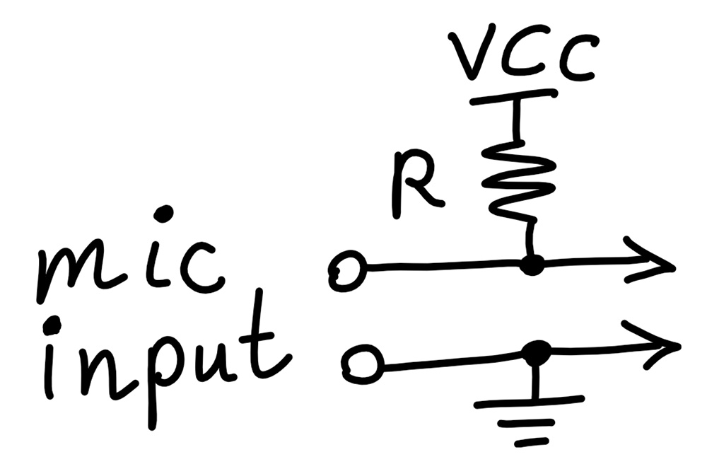
Of course here i’m not showing some protection circuit for over voltage and ESD and the rest of the recording circuit… obviously! In the case of my camera input which should be pretty standard, VCC is 2V and R is 2.2kOhm per channel.
The issue with connecting my piezo to the mic input is that the pull-up resistance is too small for the tiny power generated from the crystal, and shorts it to almost zero. The piezo can’t be loaded much to avoid the signal level drop.
I thought DC voltage from the camera across the piezo might effect the AC voltage level, and that’s why I added the capacitor as in the picture below. But that wasn’t the problem, and like I said the small pull-up resistor was the killer.
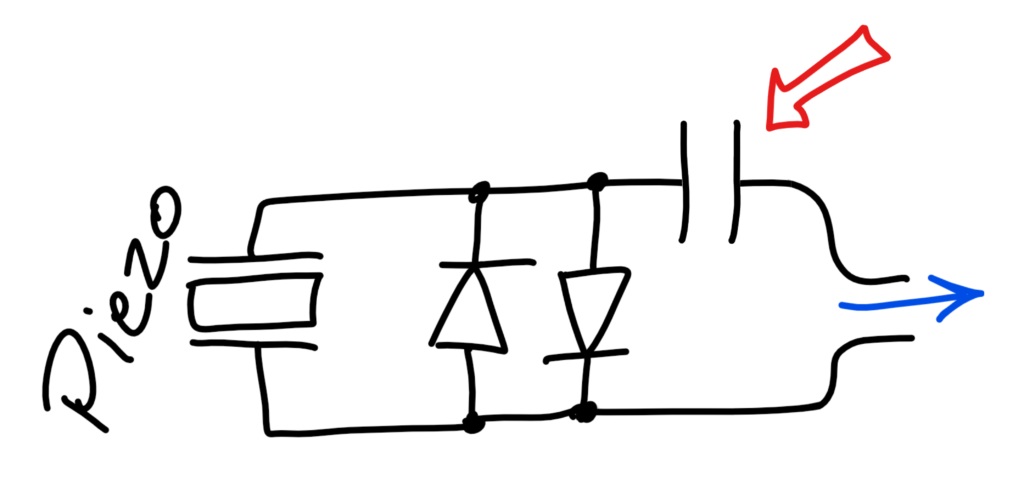
And the diodes in the above picture definitely helped protecting my camera, but without the capacitor, they would also pull the camera voltage down clamping it to around 0.7V (the forward biased diode, the one on the right). This means the diode would also clamp at least half the AC voltage too, make it even smaller if it wasn’t small enough already!
So… This tiny circuit went to trash and I put together an amplifier circuit, with very high impedance input so it wouldn’t load the weak signal at all, and would also amplify it further into a larger signal. The circuit is shown below:
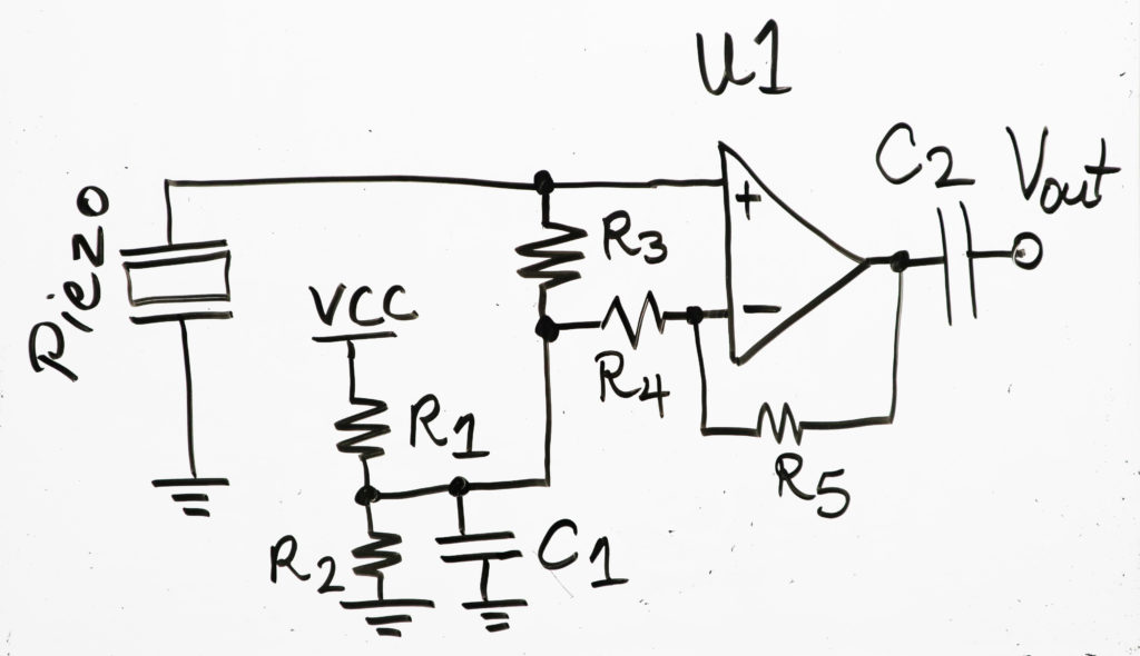
Here are the list of components I used:
- R1 and R2 = 1k Ohm (to create a reference voltage equal to VCC/2)
- C1 = 10uF (to filter noise on reference voltage)
- R3 = 220 kOhm (to apply the reference voltage to the positive input too. Like I said, piezo is like an open circuit and doesn’t provide bias current or voltage. R3 value was picked to be large to avoid loading the piezo signal much.)
- R4 = 2.2 kOhm and R5 = 220 kOhm (to create around 100x voltage gain.[Vo/Vin = (R5/R4 + 1)] The signal is in milli-volt range and this would bring it close to a volt range.)
- C2 = 10uF (to only pass AC into the microphone input of recorder, since the amplifier output voltage could be above the recorder’s voltage)
- U1: LM358N (just a general purpose operational amplifier)
- VCC = 8V (supply for reference voltage and amplifier)
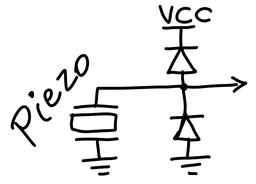
I wasn’t planning on hammering the piezo and so didn’t really bother with more protection for the amplifier chip. But I guess if you drop the microphone, there could be a voltage spike and kill the amplifier. Maybe some diode protection across the piezo doesn’t hurt after all! Something like the circuit below, that wouldn’t load the weak piezo signal either.
Simple as that! Of course I just threw this circuit together without much thought and to make a demonstration. The amplifier chip could be picked as a lower operating voltage one, maybe rail to rail output for greater output range and then a lower power supply could be used, like 3.3V. This circuit is pretty generic and can amplify anything, as long as you mind the frequency response!