As per Ray William Johnson’s Request, here I make an electric toothbrush:
Yeah, it’s not the best idea to make an electric toothbrush out of a frother, but I guess in the hours of desperation where you are in real need of an electric toothbrush to brush your teeth, and at the same time you don’t give a SH#^% about the health of your gums, you can use this method!
By the way, drop me a line if you are interested in purchasing the control circuit in form of a kit you would assemble, or an already assembled unit. I want to see if there are enough people interested in purchasing the circuit for me to put the effort into creating a package.
On the other hand, controlling a DC motor speed is something that can come in quite handy and is pretty much used everywhere.
Like I mentioned in the video, to control the speed of such a motor they use PWM, or pulse width modulation. Imagine instead of turning the motor continuously on, you turn it on an off quickly. The frequency of turning the motor on/off would be so fast that the motor would not completely turn on or off, but it would rotate at a speed that is proportional to the on-time in every period.
Now by adjusting the pulse width of the on-time in every period you can adjust the speed. And this is basically pulse width modulation.
The circuit below is what I have designed to do the PWM control of the motor:
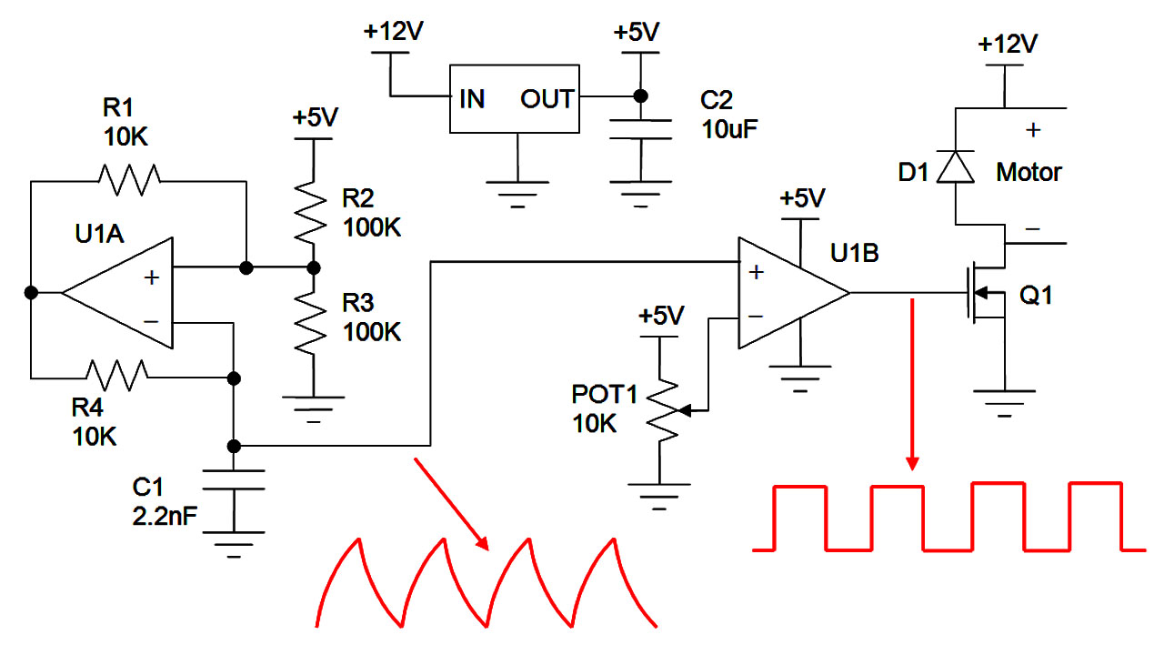
PWM control for tuning DC motor speed
There is a 5V regulator on the top center of the schematic that generates a fixed voltage. A fixed supply voltage is important to protect the control circuit, as well as keeping the circuit functionality consistent.
U1A circuit is an oscillator. The output at the capacitor is formed like a sawtooth wave. If you need a square wave instead for another application, you can use U1A output. The frequency of oscillation is tunes mainly by C1 and R4, but is also dependent on the threshold voltages the combination of R1, R2 and R3 generate when U1A output is high or low. For this circuit the frequency is roughly around 7kHz.
Sometimes the PWM frequency is adjusted to above the human hearing range to avoid creating an audible annoying tone.
U1B is a simple comparator that compares the potentiometer POT1 voltage level to the sawtooth wave and creates a square wave signal with a fixed frequency, but with a duty cycle dependent on the position of the potentiometer.
Duty cycle is the percentage of on-time over one period.
Following image shows the potentiometer level changing on the sawtooth wave and how comparing the two creates a PWM signal.
PWM Signal generated by comparing a sawtooth wave with a DC level
And finally, transistor Q1 acts like a switch that turns on and off by the PWM signal and turns the motor on and off. Diode D1 has a very important role of preventing over voltage and damaging the transistor. You know, the motor is basically an inductor and when the switch is closed, it charges to some current, and when the switch opens, it wants to continue discharging its current. But as the switch is on, the inductor can’t discharge its current and instead its voltage spikes very high. But with D1 present, the motor has a path through the diode to discharge its current and the voltage of the motor at the transistor side will not exceed the supply voltage plus a diode drop.