Changing Signals into Pulses, to Drive the Tesla Coil


I designed a circuit so I could make my oneTesla Tesla coil make sounds with my voice:

Well as you saw in the video, typical Tesla coils like oneTesla generate sound and music by interrupting the output arcs at a given frequency, usually programmed by a micro controller. If you like to see my videos on oneTesla and how it works, here they are:

In my case the micro controller was outputting pulses between 14uS to 54uS. The wider the pulses, the longer the arc and so the louder the sound.

So what I did was to replace that signal with my own. I used a regular electrec microphone and fed it into the amplifier circuit I had designed before for my Wireless Lavalier circuit. The circuit I used as amplifier looks like below. See that page for component details.

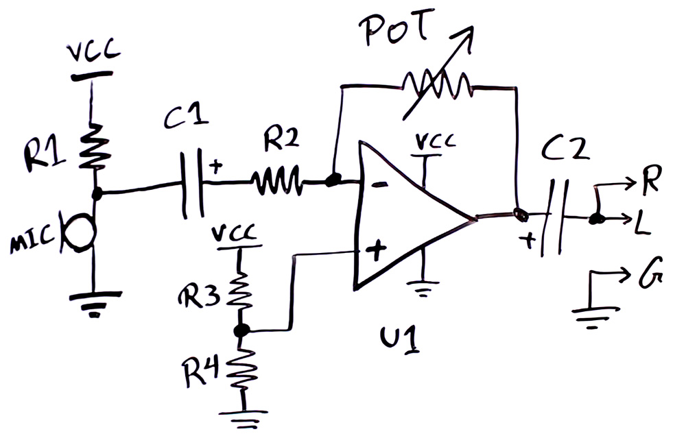
As I found out later, my circuit is susceptible to electromagnetic noise from the Tesla coil output. If you have designed a circuit for consumer use, you would know battling EMI (Electromagnetic Interference) can be a very hard task to do. But SPRINKLE CAPACITORS everywhere you shall be fine, if you are lucky!

What I would do is to add capacitors, one parallel to MIC (let’s call it C3) on the board side of the wire to get rid of noise picked by the microphone wire, one parallel to R4 (C4) and another parallel to POT (C5). C4 can be large. For high frequency 100nF could be enough, and if EMI still sucks then maybe another 10nF in parallel to C4. But for C3 and C5 you need to consider the audio frequency and make sure you don’t filter it much and ruin your audio frequency response. For C3 don’t go above 10nF and for C5 no more than 200pF (in case of my circuit, other circuits have different properties).

And then I fed the output of the amplifier into the circuit below.

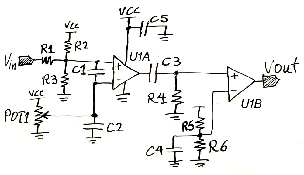
Here’s what every component does:

  • R2 and R3 provide a DC bias of around 1V that the audio input will ride on.
  • R1 combined to C1 provide signal filtering to prevent high frequency to get in.
  • POT1 provides a threshold voltage that the audio + DC bias input will be compared to by the U1A comparator. If the input signal is above the threshold, U1A output is high and otherwise low. The closer the POT1 threshold voltage is to the DC bias created by R2 and R3, the more sensitive the circuit becomes, and U1A can trigger on noise if they are too close.
  • C2 is to filter noises on POT1 threshold voltage.
  • U1A creates square wave output.
  • C3 and R4 are a high pass filter and only send out the edges of the C3 input square wave and C3 output always discharges at a fixed rate determined by the time constant RxC.
  • R5 and R6 create a fixed voltage around 1V filtered by C4, which the pulses are compared to.
  • U1B cleans up the input pulses into nice looking square pulses.
  • C5 is to filter noises on the power supply.
  • The entire circuit is powered from the output of the 5V regulator on the interrupted board.


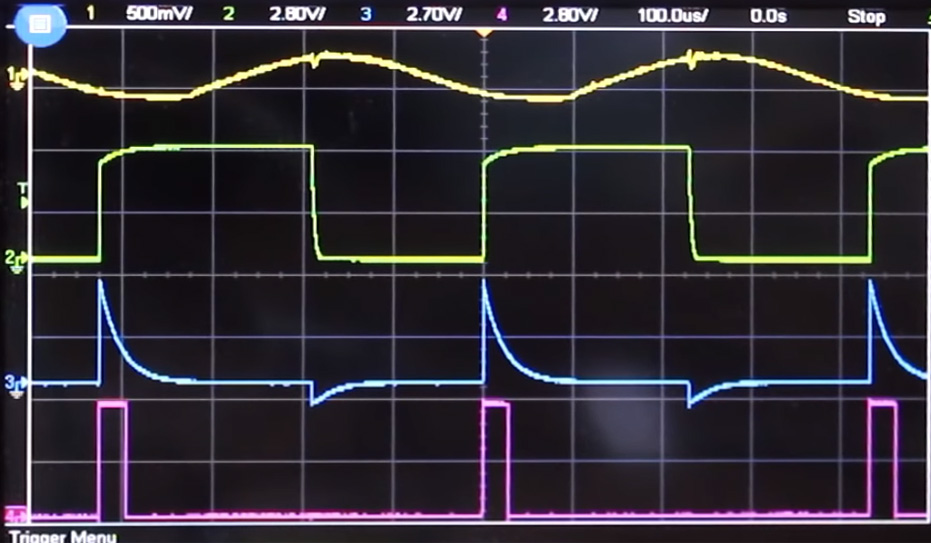
And so below are the waveforms through this circuit. From the top, we have the sinewave input, U1A output, C3 output, and U1B output.

Below are the component values:

  • R1 = 3.3k Ohm
  • R2 = R5 = 82k Ohm
  • R3 = R6 = 18k Ohm
  • C1 = C3 = 100nF
  • POT1 = 100kOhm
  • C2 = C4 = C5 = 10uF
  • U1A and U1B are in one chip MCP6562. But any comparator with push-pull output with proper frequency band (over 1MHz) would do.
  • R4 = 180 Ohm (for around 30uS pulse) You could use a potentiometer to trim as you wish.

If EMI is still an issue smaller capacitors like 100nF parallel to the 10uF capacitors should help. Remember each capacitor has an operational bandwidth and won’t filter well above that frequency. The higher the capacitance the lower the functional frequency. That’s why we put smaller capacitors parallel to larger ones, to increase the filtering capability to higher frequencies.


40 thoughts on “Changing Signals into Pulses, to Drive the Tesla Coil

  1. Why is my tesla coil resonating at 3.2 MHZ? I have added a huge top load and my secondary is a 12in. 2in diameter pvc pipe with 22 awg wire.

    • Even if the Topload is big(Capacitance) if the Inductor is small then it will ofcourse resonate at higher frequencies. So increase tower lenght or use smaller gauge wire.

  2. Hello there,

    I hope you are doing great. Let me introduce my self. My name is Alankar Nonia from India. I m a long subscriber of your channel, ElectroBOOM. Your work always inspires kids like me and who have a great interest in electrical and electronics and want to pursue it as a career. Your teaching in a fun way always makes me interested and curious. I always find you inspiring.

    My purpose of writing this email is that I need your help I m currently pursuing my electrical engineering graduation and I m working on my final year project in which require an oscilloscope.i have always been a participate in your giveaways and keysight giveaway but never have the sheer luck to win oscilloscope nor I have that much money to buy it for my self
    It’s my kind request to you, Mr. Mehdi if you could supply me with an oscilloscope, an old one, or a spare one with you anything will work for me.i will be grateful to you if you could help me in this.

    I’m looking forward to your reply, sir.

    Your loving subscribers.

  3. This is definitely fake: https://youtu.be/YDYcdJlNm1Y , but it has over 2M views and the like to dislike ratio is 25K to 2.8K. At least go over to dislike it. His entire channel is just free energy garbage, and he is making money off of people with the links to shady websites (to get the parts).

  4. Sir I connected my 9v battary to inducter to create spearks and also made lc damped oscillator…now my battery is supplying 18v ac as well as 9v dc…..I checked connecting apacitor in series to check whether it is really ac or fault of my meter….I found the ac is passing through capacitor….how can it possible….how can abattery supply ac…..please tell me…..my battery is 6f22 hi watt 9v battery for transistor radios…..

  5. Hi Medhi,
    I’ve been looking a fair bit into crystal radios recently and a design for a speaker i came across here http://www.peeblesoriginals.com/projects/crystal-loudspeaker.php mentions that having the crystal earphones and coil headphones both wired up will increase the volume from both. This seemed counterintuitive to me. If theres any chance you can give it a look i think it might be quite interesting.
    Thanks!
    Callum

  6. HI THERE!! i am from india and i watch your videos. i hope you would pay a bit attention. I wanted to make a circuit which can turn on specified led on the specified frequency respectively. i have a bike and the ignitor circuit ignite the engine after every rotation. i mean so say i can get an input signal from that circuit. there are total 12000 rpm of my engine and i want to add 12 led( for example at 1000 RPM the 1st led will glow and at 2000 RPM the second led will glow keeping ist led in ON position and so on to 12000 RPm . but i dont know how to create that circuit becasue i am not preety well in electronics. it would be appericiated if you can help me. thanks

    • It’s cool, sure. But, there are never any gases pumped into the chamber, only pulling a vacuum. The claimed temperature of 15,000,000K is complete BS: that would’ve vaporized the electrode in the center. Instead, they’re just making a corona discharge with 50,000v in a vacuum. It’s basically a super expensive-to-run desk toy.

  7. Hi electro boom I have been trying to find a car charger for my MacBook Pro. You would think this would be easy but I have fail. Apple does not sell one and after market chargers Aren’t sold in Australia. I bought a charger from batpower.com which worked for one day and cost $160 aud including postage. So it looks like I am out of options. I have seen voltage regulator on aliexpress but I would probably fry my expensive laptop. What would it take to build a 12/24 volt usb-c charger for a Mac book pro.

  8. Dear Mr Boom.

    I was wondering if you can get electric peeing on live wires. My dad said you would be the person to ask.

    Regards
    A fan

  9. Does the non inverting input U1 on the microphone amplifier drop? Because i built a similar circuit like that but the Potentiometer voltage dropped when plugged in the headphone jack.

  10. Hi Mehdi,

    Felix (my son) and me are great fans – as we were watching the 2 million special we thought we could maybe link our two Tesla Coils (2 x oneTesla TS) to a midi player such as the interupter, so we can let them play midi sounds, one lets say channel 1-4 and the other one 5-8 – we wanted to let an arduino via MoppyControl do the job, but the output signal for each channel is a square wave with a 1:1 dutycycle, so the impulses are far too intense for the Tesla coil. Do you think the circuit above could solve the problem, because i cannot figure out which program line to change in der MoppyControl source code…

    thanks for your help in advance!

    toni

  11. HI JUST WONDERING IF MOVEMENT IS NEEDED FOR A MAGNET AND
    AND COIL WHY NOT ATTACH A PIZO ELECTRIC STACK TO TME MAGNET.
    THE FREQUINCY OF THE MOVEMENT SHOULD BE MANY TIMES QUICKER
    THEN A ROTATING MOTOR. AND PIZO IS LOW POWER.
    LET ME KNOW IF IT WORKS.

    P.S IF U DO TRY .
    USING A TUBE TYPE MAGNET MAY CAUSE A PROTECTIVE FIELD .WITHIN THE TUBE

Comments are closed.