Just for the record, I had to put on some weight for this video. Otherwise I have solid abs and fantastic figure!
This device may actually work, but you better not try to make it or use it. The high voltage is hazardous, and those cheap bug f… zappers don’t follow any safety standards. After all they are made to kill! So don’t try this at home.
But this is a good reference circuit on how to sense motion, and generate and control a high voltage. Below is the schematic:
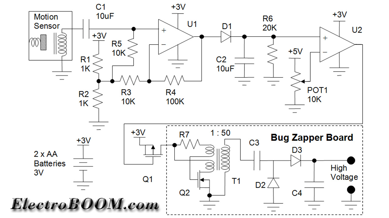 The sensor is a magnet on a spring in front of a coil. You know when you move a magnet in front of a coil, the coil generates electricity. So when the sensor is moved, it creates waves of electricity and that’s how we sense motion.
The waves from the sensor might not be large enough though and that’s why U1 circuit creates an amplifier, with a gain of almost 10x to bring the sensor signal to a more processable level.
Then the amplified signal goes through D1 diode that creates a rectifier. It creates a signal that follows the peaks of the sensor amplified voltage. This signal falls slow due to the time constant created by C2 and R6. So if the voltage after D1 rises fast when the sensor signal is high and the diode is on, it falls slow when the sensor signal drops and the diode turns off.
Now the rectified signal goes through U2 comparator and is compared with the DC level created by the potentiometer POT1. The DC level can be adjusted to tune the time we like the circuit to maintain the high voltage. The DC of POT1 should be set lower to create higher time delay.
The bug zapper board will be powered through Q1 transistor, and to turn the transistor on, the output of U2 must go low. This means the device needs to move, to create a signal level higher than POT1 DC level to set U2 output high, to keep the high voltage generator off. If the device stops moving and there is no signal from the sensor, U2 positive input drops, and falls below the POT1 DC level and U2 output goes low, turning Q1 as well as the high voltage.
Now, how does the bug zapper work? The combination of Q2, R7 and the transformer make an oscillator. Q2 switches the primary inductor on and off. Every time it turns on, it charges the primary circuit and when it turns off, the energy created reflects into secondary winding. Ideally the input and output power of the transformer is equal. So for example, let’s assume the transistor is on long enough until the primary is charged to 100mA current. In this circuit there is no permanent load on the secondary, but there is always some small leakage through components especially when the voltage is too high. Let’s assume the load is 500 kOhm.
The transformer has a 50:1 ratio, so with 100mA on primary, there will be 2mA on secondary. Therefore the output voltage will be 2mA x 500 kOhm = 1000V, which is rectified on the output components of the transformer and becomes a DC high voltage level.
The output voltage of 1000V means a 1000/50 = 20V on the primary of the transformer. So the components must be chosen to be able to handle 20V on the input, and of course 1000V on the output.